Bi-directional conduction electric-heating tube

An electric heating tube and tubular technology, which is applied in the field of bidirectional heat conduction electric heating pipes, can solve the problems of qualified rate risk, the structural design of electric heating elements cannot meet the overall development requirements of high power and small volume, and cannot bear the needs of high heat transfer, etc., to achieve life expectancy improved effect

Inactive Publication Date: 2013-03-06
张振权
View PDF10 Cites 0 Cited by
  • Summary
  • Abstract
  • Description
  • Claims
  • Application Information

AI Technical Summary

Problems solved by technology

[0003] 1. Affected by the thermal resistance characteristics of the filling material, the electric heating efficiency of the electric heating tube has never been able to meet the ideal requirements. Such products are very passive in the overall environment of low-carbon society and environmental protection.
[0004] 2. Since the thermal conductivity of the filling material has certain limitations, it cannot bear the need of high heat transfer in the state of high power density, so the structural design of the electric heating element cannot meet the overall development requirements of high power and small volume. Machine design can not be more optimized and more economical to carry out new development
[0005] 3. In magnesia (including all kinds of fused and modified magnesia), which is the most widely used filling material at present, due to the existence of many impurities such as Fe 2 o 3 , SiO 2 , CaO, Al 2 o 3 etc., the features they show at high temperature have great unreliability and stability to the thermal conductivity of the electric heating tube or the safety and leakage prevention factors, so the pass rate in the working process of the components, including the manufacturing process, is hidden. risks of

Method used


Image

  • Bi-directional conduction electric-heating tube
  • Bi-directional conduction electric-heating tube
  • Bi-directional conduction electric-heating tube

Examples


Embodiment Construction

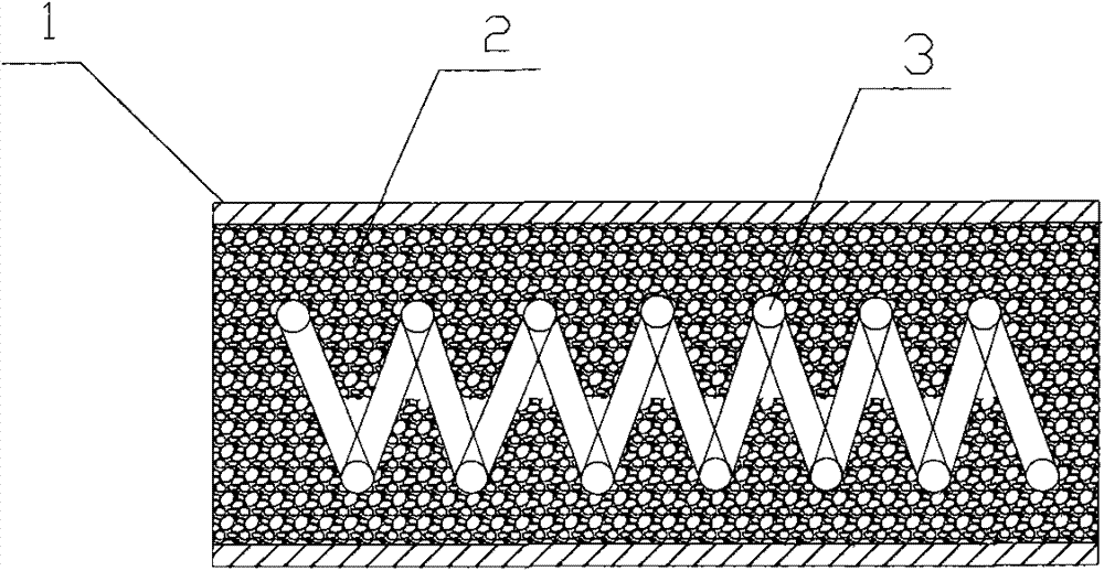
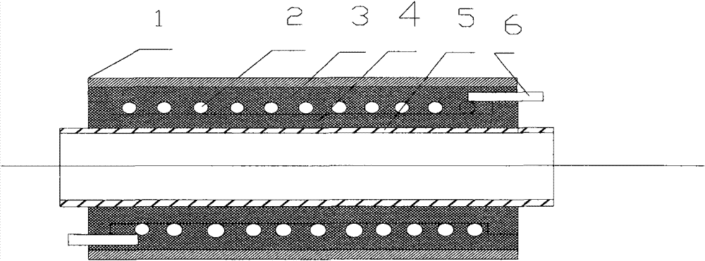
[0060] see image 3 When the working voltage is applied to the lead rod 6 shown in the figure, the heating wire 2 connected to the lead rod 6 generates heat, and the heat is transferred to the metal tubes 1 and 5 through the filling materials 3 and 4, so that they are respectively connected to the heated Heat exchange occurs in the medium.

[0061] see Figure 5 ; The working principle of the device shown in the figure is introduced as follows: It is a schematic diagram of a multi-power product. Although the structure in the figure is an integral component, it can realize four different powers, that is, use the inner side alone The power of P1 can be obtained when the heating wire is 8, and the power obtained when the heating wire 4 is used alone is P2. If the heating wire 4 and 8 are connected in series, the power obtained is P3. Similarly, if the heating wire 4 and 8 are connected in parallel to obtain The power is P4. The principle is that the biggest difference from the...


PUM


Abstract

A bi-directional conduction electric-heating tube comprises a metal outer tube, a metal inner tube, filler, a heating wire and a guide bar. The heating wire with the guide bar is disposed between the metal outer tube and the metal inner tube. The heating wire is fixed between the metal outer tube and the metal inner tube through the filler. The bi-directional conduction electric-heating tube has the advantages that electric heating efficiency is improved, and radiating area is also enlarged.

Description

technical field [0001] The invention relates to the field of electric heating, in particular to a bidirectional heat conduction electric heating tube. Background technique [0002] Metal electric heating tube is currently the most used energy conversion device for small household appliances in the world, that is, it completes the conversion of electric energy to thermal energy. Although a huge leap has taken place in the electric heating industry from quantity to quality since the 1990s, this The use of class components still has the following unsatisfactory conditions: [0003] 1. Affected by the thermal resistance characteristics of the filling material, the electric heating efficiency of the electric heating tube has never been able to meet the ideal requirements. Such products are very passive in the overall environment of a low-carbon society and environmental protection. [0004] 2. Since the thermal conductivity of the filling material has certain limitations, it can...

Claims


Application Information

Patent Timeline
Patent Type & Authority Applications(China)
IPC IPC(8): H05B3/48
Inventor 盛建寅张振权
Owner 张振权
Why Eureka
Try Eureka