
Laser light source and lighting device

A laser light source and laser diode technology, applied in the field of lighting, can solve the problems of not fully utilizing the advantages of the fixed plate to transmit heat, the temperature of the fluorescent sheet is too high, and the conduction efficiency is low, so as to reduce heat accumulation, prolong the life of the fluorescent sheet, and speed up the The effect of efficiency

Pending Publication Date: 2022-03-04
SHANGHAI BLUE LAKE LIGHTING TECH CO LTD
View PDF0 Cites 0 Cited by
  • Summary
  • Abstract
  • Description
  • Claims
  • Application Information

AI Technical Summary

Problems solved by technology

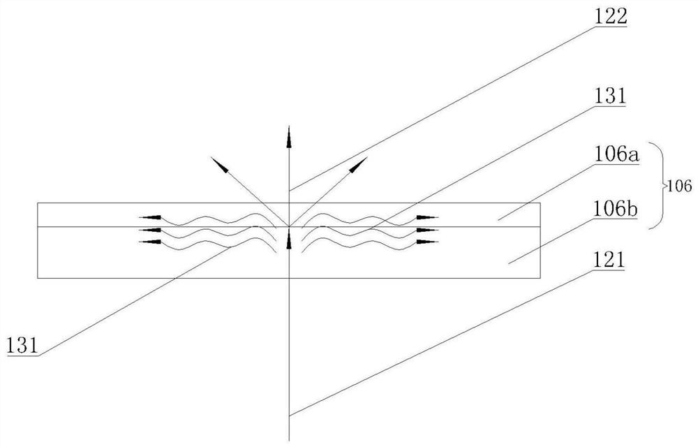
[0003] There are still many shortcomings in the practical application of laser lighting devices, for example, in the heat dissipation of fluorescent sheets, such as figure 1 As shown, the existing technical solutions for heat dissipation mainly rely on the substrate in the fluorescent sheet to transfer heat. The main heat of the above heat dissipation method is still concentrated on the fluorescent sheet. Although the substrate can transfer heat to the outside of the system, the overall temperature of the fluorescent sheet is still relatively high. high
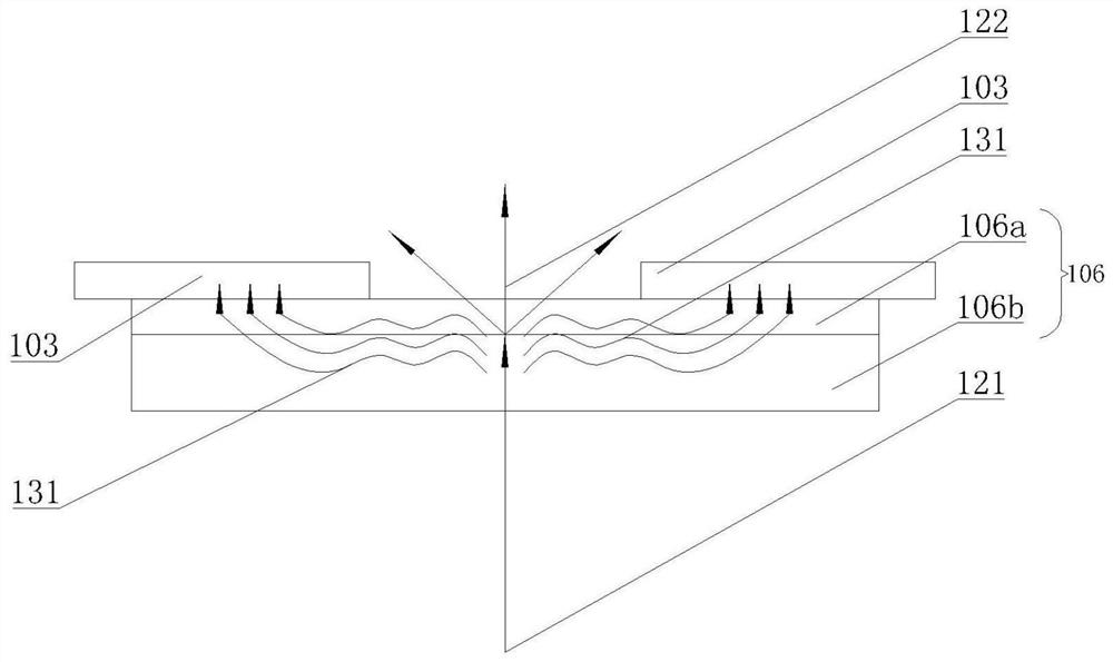
like figure 2 As shown, according to the above problems, the existing solution is to fix one side of the fluorescent sheet on the heat dissipation device by bonding or other fixing methods. The center excited by the laser diffuses to the periphery, and then conducts to the side connected to the heat sink until it is conducted to the fixed plate. This technical solution adds a fixed plate to transmit the heat generated by the laser-excited fluorescent sheet, but the disadvantage of the above technical solution is that, The distance of heat transfer from the fluorescent sheet to the fixed plate is long, the conduction efficiency is low, and the advantage of the heat transfer of the fixed plate is not fully utilized

Method used


Image

  • Laser light source and lighting device
  • Laser light source and lighting device
  • Laser light source and lighting device

Examples


Embodiment

[0026] Such as Figure 3-7 As shown, a laser light source includes a laser diode emitting laser light 121 and a fluorescent sheet 106 excited by the laser diode. The fluorescent sheet 106 includes a transparent thermally conductive substrate 106b and a fluorescent material 106a covered on the surface of the substrate 106b. It also includes a fixing plate 102 and a fixing block 103 for fixing the fluorescent sheet 106. Since the fixing block 103 is used to transfer the heat 131 of the fluorescent sheet 106 to the fixing plate 102, the fixing block 103 needs to be connected with the fluorescent sheet 106 and the fixing plate 102. Therefore, the fixing block 103 is disposed on the fixing plate 102 . The fixed block 103 is in direct contact with the fixed plate 102, and the heat transfer speed is fast and the heat transfer efficiency is high; for example, preferably, the fixed block 103 and the fixed plate 102 are integrally formed, and there is no interface between the two at thi...


PUM


Abstract

The invention discloses a laser light source and a lighting device, the laser light source comprises a laser diode, a fluorescent sheet excited by the laser diode, a fixing plate for fixing the fluorescent sheet and fixing blocks, at least one fixing block is arranged on the fixing plate, the side edge of the fluorescent sheet is connected with the adjacent fixing block, and a heat-conducting medium is filled between the side edge of the fluorescent sheet and the adjacent fixing block. A light passing opening is formed in the fixing plate and covers the area, excited by the laser, of the fluorescent piece, and at least part of the area of the fluorescent piece abuts against the area, located on the edge of the light passing opening, of the fixing plate. According to the laser lighting device, the heat transfer distance is shortened through lateral heat conduction of the fluorescent piece, the heat transfer efficiency is improved, heat accumulation is reduced, the service life of the fluorescent piece is prolonged, and therefore the service life of the whole laser lighting device is prolonged. According to the laser lighting device, the heat transfer distance is shortened through lateral heat conduction of the fluorescent piece, the heat transfer efficiency is improved, heat accumulation is reduced, the service life of the fluorescent piece is prolonged, and therefore the service life of the whole laser lighting device is prolonged.

Description

technical field [0001] The invention relates to the technical field of illumination, in particular to a laser light-emitting device that dissipates heat through the side edge of a fluorescent sheet, and an illumination device that uses the laser light-emitting device to emit light. Background technique [0002] The use of lasers for lighting and display is an emerging industry. In the field of lighting, semiconductor lighting technology represented by white LEDs has become the main light source in the field of lighting due to its advantages of high efficiency, energy saving, long life, environmental protection, safety and reliability. However, blue LED chips are characterized by a sharp drop in efficiency. Therefore, large lumens and high power white light lighting devices can only be realized by increasing the number of LEDs. White laser lighting is developed to make up for the demand of white LEDs in the field of ultra-high power and ultra-high brightness lighting, and ha...

Claims


Application Information

Patent Timeline
IPC IPC(8): F21K9/20F21K9/64F21V9/32F21V19/00F21V29/503F21V29/71F21Y115/30
CPCF21K9/20F21K9/64F21V9/32F21V19/00F21V29/503F21V29/71F21Y2115/30
Inventor 杨毅
Owner SHANGHAI BLUE LAKE LIGHTING TECH CO LTD
Learn More