
A mobile energy storage device using superconducting heat pipes and copper foam phase change materials

A technology of superconducting heat pipes and phase change materials, applied in the field of energy storage, can solve the problems of high pressure in the sealed cavity, low heat transfer efficiency, slow thermal response, etc., and achieve the effects of safe and reliable work, high heat transfer efficiency, and increased thermal conductivity

Active Publication Date: 2018-06-19
上海绚光节能环保科技股份有限公司
View PDF7 Cites 0 Cited by
  • Summary
  • Abstract
  • Description
  • Claims
  • Application Information

AI Technical Summary

Problems solved by technology

[0004] Most of the existing phase change heat storage devices that use phase change materials for waste heat recovery and utilization have problems such as low heat transfer efficiency, slow thermal response, high internal pressure of the sealed cavity, complex structure, and large volume.

Method used


Image

  • A mobile energy storage device using superconducting heat pipes and copper foam phase change materials
  • A mobile energy storage device using superconducting heat pipes and copper foam phase change materials
  • A mobile energy storage device using superconducting heat pipes and copper foam phase change materials

Examples


Embodiment 1

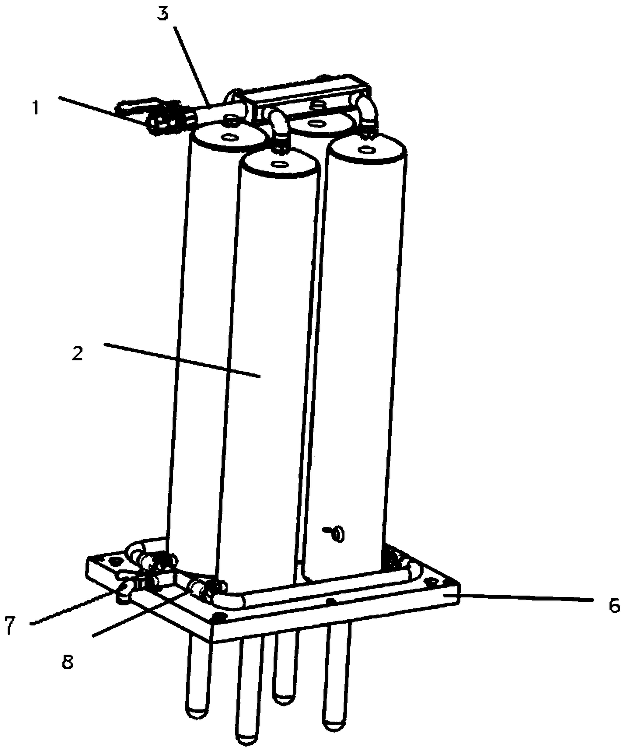
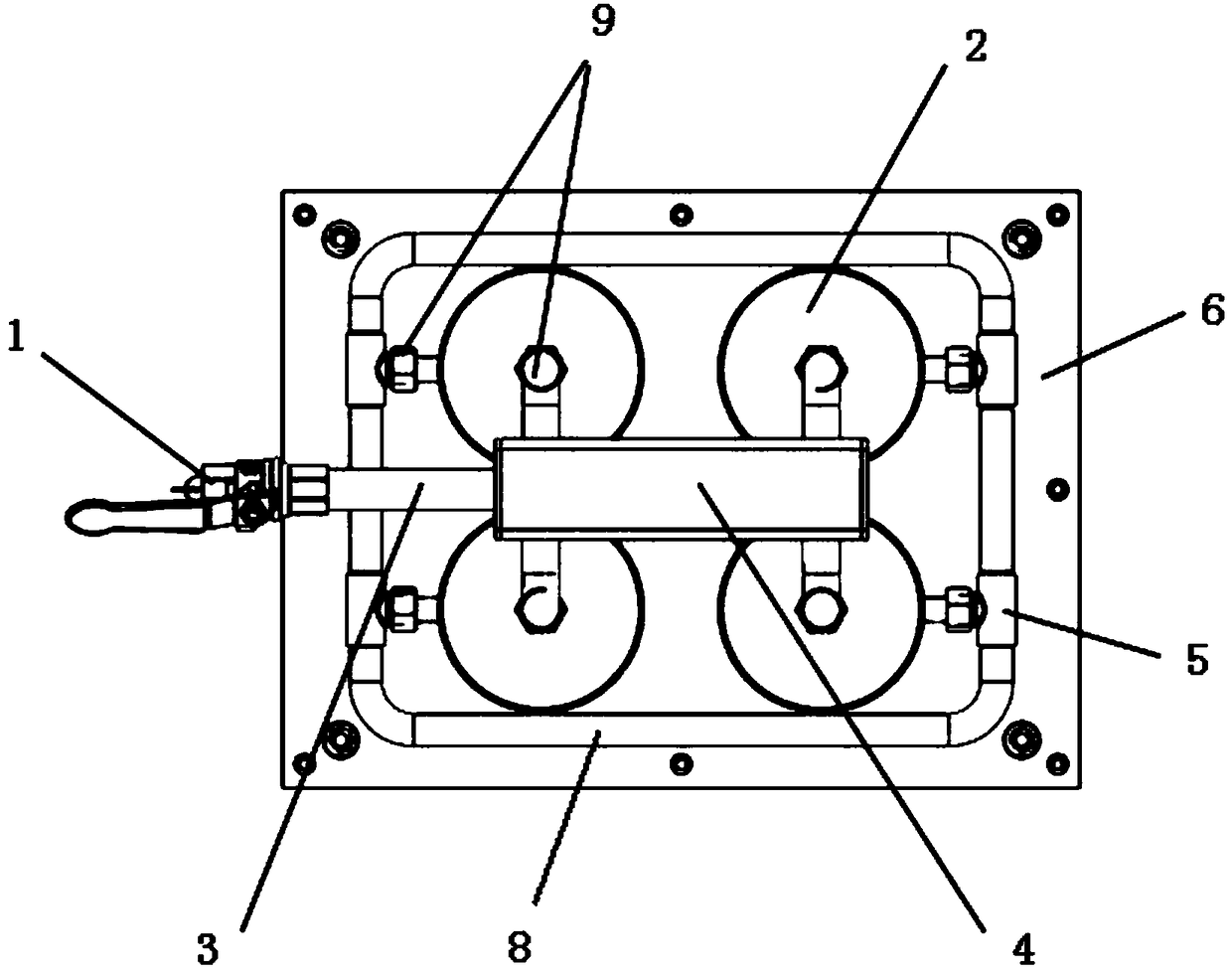
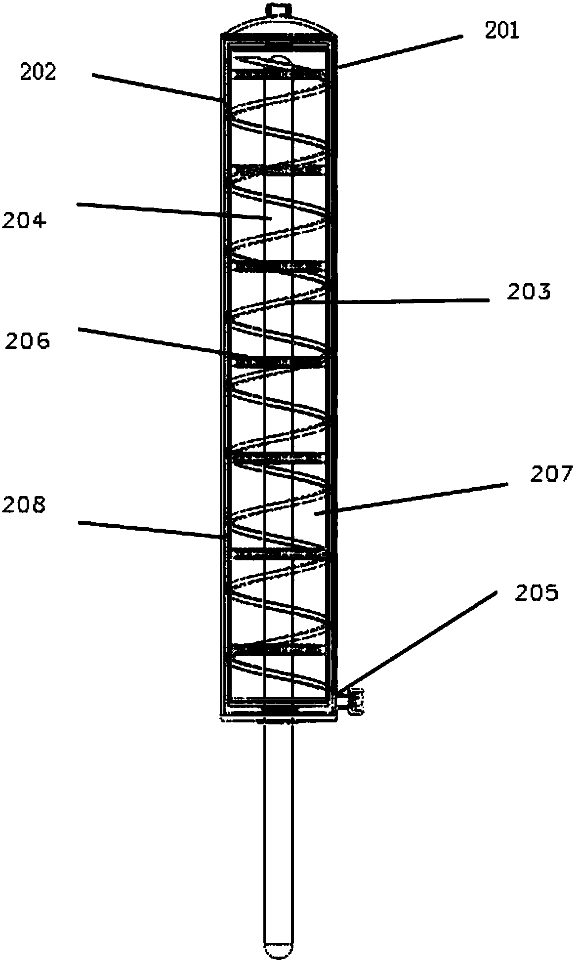
[0036] Such as figure 1 , figure 2 As shown, the present invention is a mobile energy storage device using a superconducting tube and a foamed copper phase change material, which includes a plurality of monomer phase change heat accumulators 2 connected in parallel; image 3 , Figure 4 As shown, the single phase change heat accumulator 2 includes a closed cylindrical shell, the cylindrical shell is divided into three layers, respectively, an outer layer of stainless steel sleeve 201, an inner layer of copper sleeve 208, and The interlayer 202 between the outer stainless steel sleeve and the inner copper sleeve; the upper end of the cylindrical shell is provided with a water inlet, which communicates with the interlayer; the lower side of the cylindrical shell is provided with a water outlet, and the water outlet is connected with The interlayer is connected; the interlayer 202 (ie, the cold water channel) is provided with a spiral guide ring 203, which can make the cold water ...


PUM

PropertyMeasurementUnit
pore sizeaaaaaaaaaa
porosityaaaaaaaaaa
porosityaaaaaaaaaa

Abstract

The invention discloses a novel movable type energy storage device using superconductive tubes and copper foam phase-change materials. The novel movable type energy storage device using the superconductive tubes and the copper foam phase-change materials comprises a plurality of parallel single phase-change heat accumulators, wherein each single phase-change heat accumulator comprises a closed cylindrical shell; each shell comprises an outer sleeve, an inner metal sleeve and an interlayer; the interlayer of each shell is a cold water channel; a spiral guide ring is arranged in the interlayer of each shell; a superconductive tube is arranged in each shell; the upper end of each superconductive tube is sealed and inserted in the upper part of the inside of the corresponding shell; the lower end of each superconductive tube is open, is exposed outside the corresponding shell and is connected with a waste heat source; a phase-change material which is used for filling holes of copper foam is used for filling between the corresponding inner sleeve and the corresponding superconductive tube; the single phase-change heat accumulators are erected side by side; a water inlet of the upper end of each single phase-change heat accumulator is connected with a water inlet tube through a water collecting square tube; and a water outlet of the lower end of each single phase-change heat accumulator is connected with a water outlet tube through a three-way tube. The novel movable type energy storage device recycles the waste heat by the superconductive tubes, and is quick in heat transmission and high in heat conduction efficiency; and by the copper foam, the heat conduction coefficient of the phase-change materials is improved by the copper foam, and heat storage rate and heat release rate are increased.

Description

Technical field [0001] The invention belongs to the technical field of energy storage, and relates to a mobile energy storage device adopting a super heat-conducting tube and a foamed copper phase change material. Background technique [0002] The recovery rate of industrial waste heat and waste heat in traditional steel, chemical, electric power and other high-energy and high-emission industries is very low. For example, low-temperature waste heat such as diffuse steam waste heat, slag-washing water waste heat, flue gas waste heat, compressed air waste heat, etc. has not been developed Utilization, which leads to a large amount of energy being consumed every year, and a large amount of gas emissions. At the same time, waste heat and waste heat recovery are still less utilized in the commercial and civilian markets, and most waste heat utilization projects are still insufficient in economy and flexibility. [0003] Today, energy conservation has obviously become an important socia...

Claims


Application Information

Patent Timeline
Patent Type & Authority Patents(China)
IPC IPC(8): F28D20/02
CPCF28D20/021Y02E60/14
Inventor 周阳倪国胜
Owner 上海绚光节能环保科技股份有限公司
Learn More