Ball joint

A ball joint and spherical shell technology, applied in the field of ball joints, can solve problems such as insufficient fracture resistance of ball joints, and achieve the effect of improving performance

Active Publication Date: 2013-03-06
ZF FRIEDRICHSHAFEN AG
View PDF5 Cites 3 Cited by
  • Summary
  • Abstract
  • Description
  • Claims
  • Application Information

AI Technical Summary

Problems solved by technology

[0004] Insufficient fracture resistance of the ball joint at higher axial loads

Method used


Image

  • Ball joint
  • Ball joint
  • Ball joint

Examples


Embodiment Construction

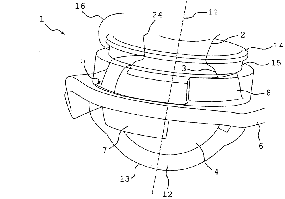
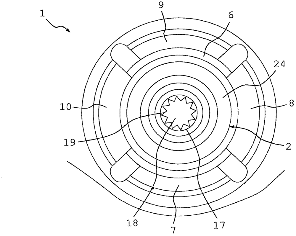
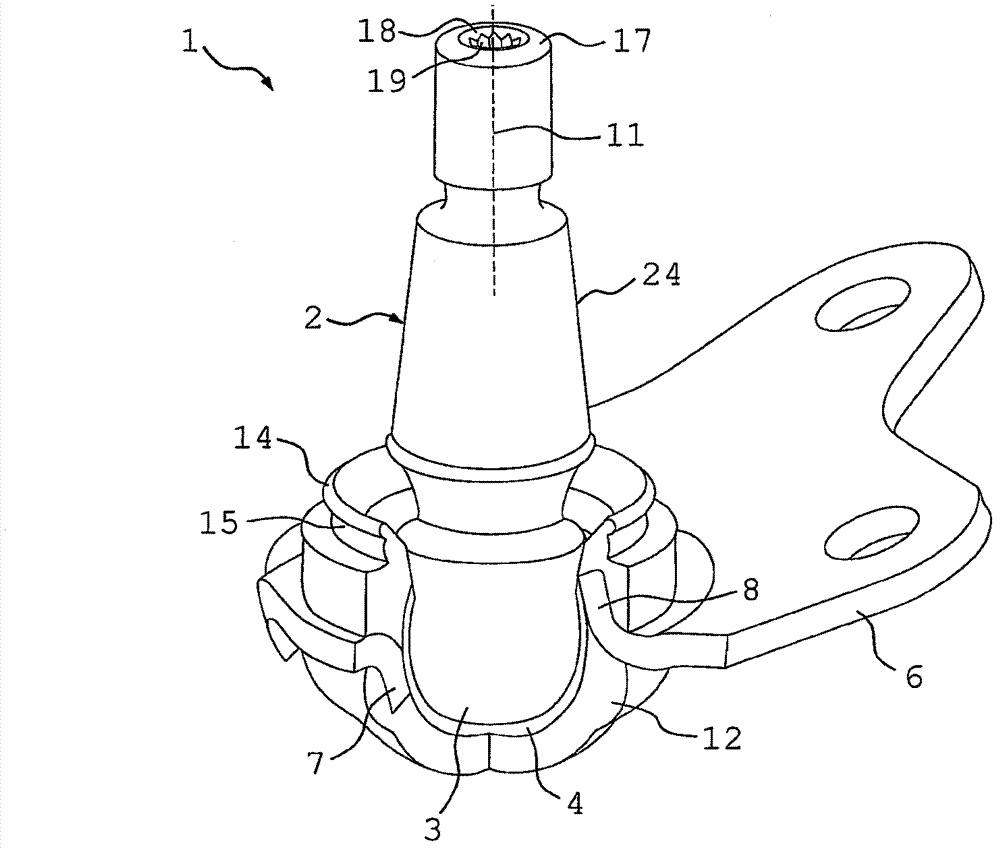
[0029] from Figures 1 to 3 A different view of a ball joint 1 according to a first embodiment of the invention can be seen in FIG. It is slidably mounted in the ball housing 4 . The ball pin 2 is rotatably and pivotally engaged in a ball housing 4 which is arranged in a through-bore 5 of the carrier 6 . The bracket 6 surrounds the undeflected ball pin 2 at the level of the equator of the joint ball 3 , so that the bracket 6 can absorb radial forces introduced on the ball pin 2 . Edge sections 7 , 8 , 9 and 10 are bent out of the carrier 6 , which extend obliquely with respect to the axial direction 11 and cover the ball housing axially with their free ends. 4. In this case, the edge sections are bent alternately in opposite directions, wherein, according to the illustration, edge sections 8 and 10 extend upward and edge sections 7 and 9 extend downward. Before the part formed by the spherical shell 4 and the ball pin 2 is inserted into the hole 5 , the edge section or at ...


PUM


Abstract

The invention relates to a ball joint having a ball journal (2) comprising a spherical bearing region (3), wherein said ball journal is mounted by means of the bearing region (3) in a slidingly displaceable manner in a ball socket (4) and disposed with same in an opening (5) of a mounting element (6), and a solid body (12) formed by encapsulating the ball socket (4) and the mounting element (6) in a solidifiable material, from which the ball journal (2) extends outward in an axial direction (11), wherein an axial retainer for the ball journal (2), which axially covers the ball socket (4) and is encapsulated by the material, is provided in the solid body (12).

Description

technical field [0001] The invention relates to a ball joint with a ball pin having a spherical bearing region, by means of which the ball pin is slidably mounted in a ball housing and is arranged together with the ball housing in a bore of a carrier and a solid body formed by encapsulating the spherical shell and the bracket with a hardenable material, from which the ball pin extends in the axial direction. Background technique [0002] The construction and assembly of ball joints configured as radial joints is based on the production and joining of individual parts (ball pin, ball shell, housing, bellows seal, etc.) in one process and processing step. The overall function and properties of the radial joint are determined by the respective tolerance ranges of the individual parts and optimized by subsequent processes (heat treatment, grinding, etc.) to meet customer requirements. [0003] Document EP 0 927 310 B1 discloses a ball joint with a ball joint housing which has a...

Claims


Application Information

Patent Timeline
Patent Type & Authority Applications(China)
IPC IPC(8): F16C11/06
CPCF16C11/0638F16C11/069F16C11/0685B60G2204/416B60G2204/42B60G2204/4404Y10T403/32631F16C11/06
Inventor F·纳赫巴V·格鲁贝C·格罗内韦格T·霍德
Owner ZF FRIEDRICHSHAFEN AG
Why Eureka
Try Eureka