
Segmented elastomeric vibration mount with edge control

An elastic layer and flange technology, applied in the field of segmented elastic vibration supports, can solve problems such as support failure, and achieve the effect of enhancing durability and bearing capacity

Inactive Publication Date: 2013-03-06
PULLMAN INC
View PDF0 Cites 1 Cited by
  • Summary
  • Abstract
  • Description
  • Claims
  • Application Information

AI Technical Summary

Problems solved by technology

These higher stress levels can lead to premature failure of the stent

Method used


Image

  • Segmented elastomeric vibration mount with edge control
  • Segmented elastomeric vibration mount with edge control
  • Segmented elastomeric vibration mount with edge control

Examples


Embodiment Construction

[0018] Example embodiments will now be described more fully with reference to the accompanying drawings.

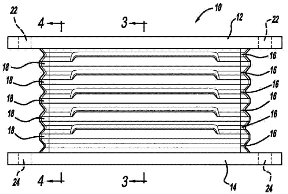
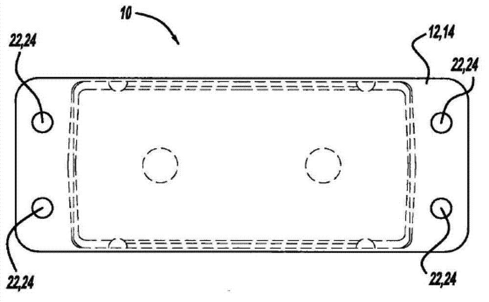
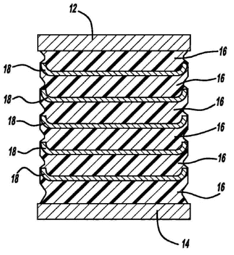
[0019] see Figure 1 to Figure 4 , a bracket assembly according to the present disclosure is illustrated and generally indicated by the reference numeral 10 . The bracket assembly 10 includes a first mounting plate 12 , a second mounting plate 14 , a plurality of elastic layers 16 and a plurality of spacers 18 .

[0020] The first mounting plate 12 is a generally rectangular plate having a plurality of mounting holes 22 extending through the first mounting plate 12 . The bracket assembly 10 is designed to be placed between two components and a plurality of mounting holes 22 are provided to receive suitable fasteners to attach the first mounting plate 12 to one of the two components. The second mounting plate 14 is a generally rectangular plate having a plurality of mounting holes 24 extending through the second mounting plate 14 . A plurality of mounting holes 24 are p...


PUM


Abstract

A mount assembly has a plurality of elastomeric members having a separator plate disposed between adjacent elastomeric members. The separator plate defines a flange which extends toward an adjacent separator plate to confine the elastomeric layer. A mounting plate is located at both ends of the mount assembly and can be used to attach the mount assembly to two components.

Description

technical field [0001] The present disclosure relates to a segmented elastic vibration support. More specifically, the present disclosure relates to a segmented elastic vibration mount with edge control embedded in plates disposed between elastic layers. Background technique [0002] This section provides background information related to the present disclosure which is not necessarily prior art. [0003] Brackets with load-bearing and deflection capabilities are used in applications such as vehicle suspensions connecting axles to vehicle frames, seismic isolation systems, mechanical mounts, electrical equipment isolation, packaging, and other applications requiring load-bearing and deflection capabilities. These elastic mounts are designed to withstand compressive and tensile loads, while simultaneously allowing translation and tilting of the two components relative to each other. Typically, resilient mounts utilize circulating layers of resilient material, such as natura...

Claims


Application Information

Patent Timeline
IPC IPC(8): F16F15/04F16F15/02B60K5/12
CPCF16F1/403F16F15/04F16F15/08B60K5/12
Inventor 罗纳德·J·麦克劳克林
Owner PULLMAN INC
Learn More