Solar cell array

A technology of solar cells and arrays, applied in the field of solar cell arrays, which can solve problems such as excessive construction hours and raw materials, and the inability to arrange solar cell modules beautifully

Active Publication Date: 2013-03-06
KYOCERA CORP
View PDF5 Cites 4 Cited by
  • Summary
  • Abstract
  • Description
  • Claims
  • Application Information

AI Technical Summary

Problems solved by technology

In this case, two or more fixing members are required for one solar cell module, which may require a lot of construction man-hours and raw materials
[0005] In addition, even if such fixing members are arranged at the corners of the solar cell modules, when the roof is tilted, the solar cell modules may not be arranged beautifully.

Method used


Image

  • Solar cell array
  • Solar cell array
  • Solar cell array

Examples


no. 1 approach

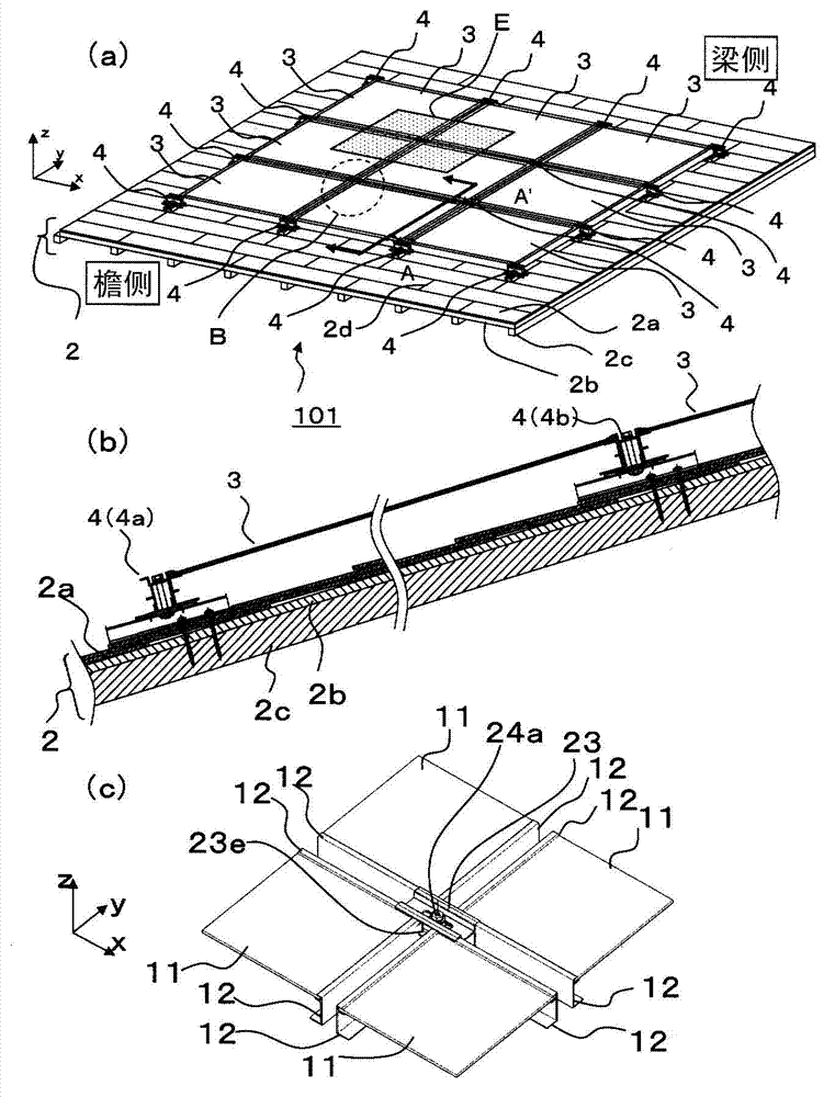
[0026] Such as figure 1 As shown in (a) and (b), the solar cell array 101 has a plurality of solar cell modules 3 and mounting members 4 . Such a solar cell array 101 is fixed to the base 2 (roof surface) including the roof panel 2a, the roof panel 2b, and the rafters 2c. In addition, the plurality of solar cell modules 3 are arranged so as not to overlap with each other with the back surface thereof as the lower side. In this embodiment, if figure 1 As shown in (a), a plurality of solar cell modules 3 are arranged along two directions, the Y direction which is the direction in which the inclined surface 2 is inclined, and the X direction perpendicular to the Y direction.

[0027]

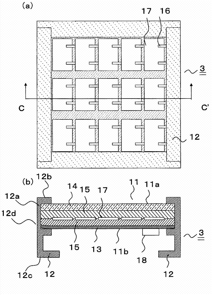
[0028] Such as figure 2 As shown, the solar cell module 3 has a solar cell panel 11 and a frame 12 .

[0029] Such as figure 2 As shown in (b), the solar cell panel 11 has a light-receiving surface 11a (one main surface of the light-transmitting substrate 14) that mainly receives light, an...

no. 2 approach

[0094] Next, use Figure 8 to Figure 10 , the solar cell array 201 of the second embodiment will be described in detail. It should be noted that description of the same configuration as that of the first embodiment will be omitted.

[0095]

[0096] Such as Figure 8 As shown, the solar cell array 201 of this embodiment further includes the eaves side member 5 for fixing the eaves side frame 12e of the solar cell module 3 arranged at the lowermost part in the inclined Y direction.

[0097] It should be noted that, in this embodiment, if Figure 8 As shown, hereinafter, the inclined direction of the base 2 is referred to as the Y direction, the direction normal to the base 2 is referred to as the Z direction, and the direction perpendicular to the Y direction and the Z direction is referred to as the X direction. In addition, among the solar battery modules 3 adjacent along the Y direction, the solar battery module located at the bottom (most on the front side of the eaves...

no. 3 approach

[0132] Next, use Figure 11 (a) and (b) illustrate the solar cell array 301 of the third embodiment.

[0133] Such as Figure 11 As shown in (a), the solar cell array 301 of the third embodiment is different from the solar cell array 201 of the second embodiment in the structure of the protective member 33 .

[0134] In this embodiment, the cross section of the hollow portion 33c of the protective member 33 cut along the direction perpendicular to the longitudinal direction of the track groove 33a is a quadrangular closed cross section.

[0135] In this way, the torsional rigidity is approximately doubled compared to the case of a hollow triangular cross-section having approximately the same size. Thereby, the strength of the eaves front side of the solar cell array 301 can be greatly improved.

[0136] In addition, in order to improve appearance, the hollow part 23c may be the cross-sectional shape of the trapezoid which has a hypotenuse at the front side of the hollow par...


PUM


Abstract

Disclosed is a solar cell array that requires a reduced number of man-hours to manufacture, requires fewer resources, and exhibits improved reliability. Said solar cell array is provided with: a plurality of solar-cell modules that are arranged, with the back sides thereof facing down and without overlapping each other, in an X direction and / or a Y direction orthogonal to the X direction; and attachment members disposed between corners of adjacent solar-cell modules. Said attachment members comprise: first members that extend in the aforementioned X direction and / or the aforementioned Y direction; second members that are positioned on top of the first members and have support parts that support the back sides of the solar-cell modules; third members that are positioned on top of the second members and have clamp members that clamp the support parts of the second members and the solar-cell modules; and affixing members that vertically penetrate the second and third members and affix said second and third members to the first members. The second and third members can move lengthwise along the first members.

Description

technical field [0001] The present invention relates to solar cell arrays. Background technique [0002] The solar cell array has a plurality of solar cell modules and a stand for fixing the plurality of solar cell modules. Usually, an elongated structural member is provided on the roof of a house as a stand on which the opposite sides of the solar cell module are fixed over the entire length. [0003] Also, as disclosed in JP 2004-324181 A, a solar cell array is proposed in which a solar cell module is fixed to a roof with a small fixing member instead of a thin and long structural member. [0004] However, such a solar cell array fixes the opposite sides of adjacent solar cell modules with fixing members. Therefore, the self-weight, snow load, and wind load of about half the area of ​​the solar cell module are supported at each location of the fixing member. In this case, two or more fixing members are required for one solar cell module, which may require many construct...

Claims


Application Information

Patent Timeline
Patent Type & Authority Applications(China)
IPC IPC(8): H01L31/042E04D13/18
CPCF24J2/5245F24J2/5264F24J2/5254F24J2002/5281F24J2002/0046Y02E10/50H01L31/048F24J2/5211H01L31/0482Y02B10/12Y02E10/47F24J2/5207H02S20/23F24S25/61F24S25/632F24S25/35F24S2025/014F24S2025/601F24S25/20F24S2020/11F24S25/70Y02B10/10
Inventor 神原达二平田浩显
Owner KYOCERA CORP
Why Eureka
Try Eureka