A beam-wire dislocation laser-mag composite welding method for corner joints of medium and thick plates

A composite welding and welding wire technology, which is applied in the field of beam-welding wire misalignment laser-MAG composite welding of medium and thick plate corner joints, can solve the problems of great influence on the preparation accuracy and welding quality, uneven surface welds, and incomplete penetration of back welds, etc. problems, to achieve the effects of improving mechanical properties and sealing performance, narrowing the heat-affected zone, and reducing residual deformation and residual stress

Active Publication Date: 2019-04-12
HARBIN INST OF TECH
View PDF7 Cites 0 Cited by
  • Summary
  • Abstract
  • Description
  • Claims
  • Application Information

AI Technical Summary

Problems solved by technology

[0013] The invention aims to solve the problems of poor welding adaptability, uneven surface weld seam, poor flatness, incomplete penetration of the back weld seam, discontinuous forming, undercut, and excessive heat input in the laser-MAG composite welding process of medium and thick plate corner joints. The overall collapse, assembly accuracy and material preparation accuracy, especially the gap and misalignment, have a great influence on the welding quality, especially when the assembly accuracy is not high, the side of the back vertical plate is forced to form by surfacing welding, and the joint is not melted. In order to solve the problem of the overall weld, a beam-wire dislocation laser-MAG hybrid welding method for the corner joint of medium and thick plates is proposed

Method used


Image

  • A beam-wire dislocation laser-mag composite welding method for corner joints of medium and thick plates
  • A beam-wire dislocation laser-mag composite welding method for corner joints of medium and thick plates
  • A beam-wire dislocation laser-mag composite welding method for corner joints of medium and thick plates

Examples


specific Embodiment approach 1

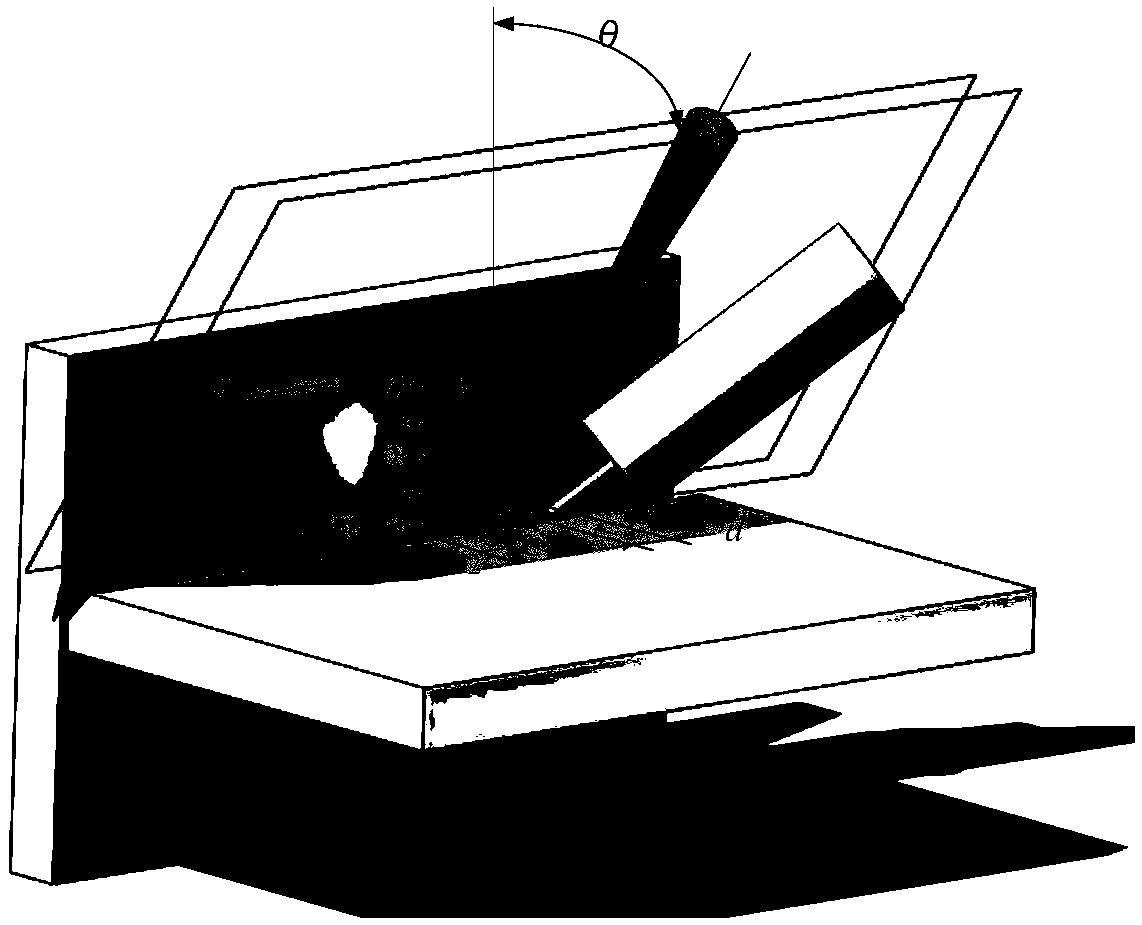
[0039] Specific implementation mode 1: using laser beam-welding wire dislocation laser-MAG composite welding medium and thick plate fillet joints, the laser can use CO 2 Gas lasers, YAG solid-state lasers, semiconductor lasers, fiber lasers, etc. Among them, YAG solid-state lasers, semiconductor lasers or fiber lasers that use optical fiber transmission have the best welding effect because they are more flexible and efficient. MAG adopts the Fronius TPS4000 MAG arc welding machine, and assembles and connects the fiber laser-MAG composite welding head with the Kuka robot.

[0040] Step 1: Process the part to be welded of the workpiece (horizontal plate in the fillet joint) into a single V-shaped groove, a single U-shaped groove, a single Y-shaped groove or a single U-shaped groove with a blunt edge as required, and Grind or clean the processed single-sided groove, the surfaces on both sides, and the surface of the vertical plate, and fix the polished or cleaned workpiece to be ...

specific Embodiment approach 2

[0049] Embodiment 2: The difference between this embodiment and Embodiment 1 is that the laser is CO 2 Gas laser, YAG solid-state laser, semiconductor laser or fiber laser. Others are the same as in the first embodiment.

specific Embodiment approach 3

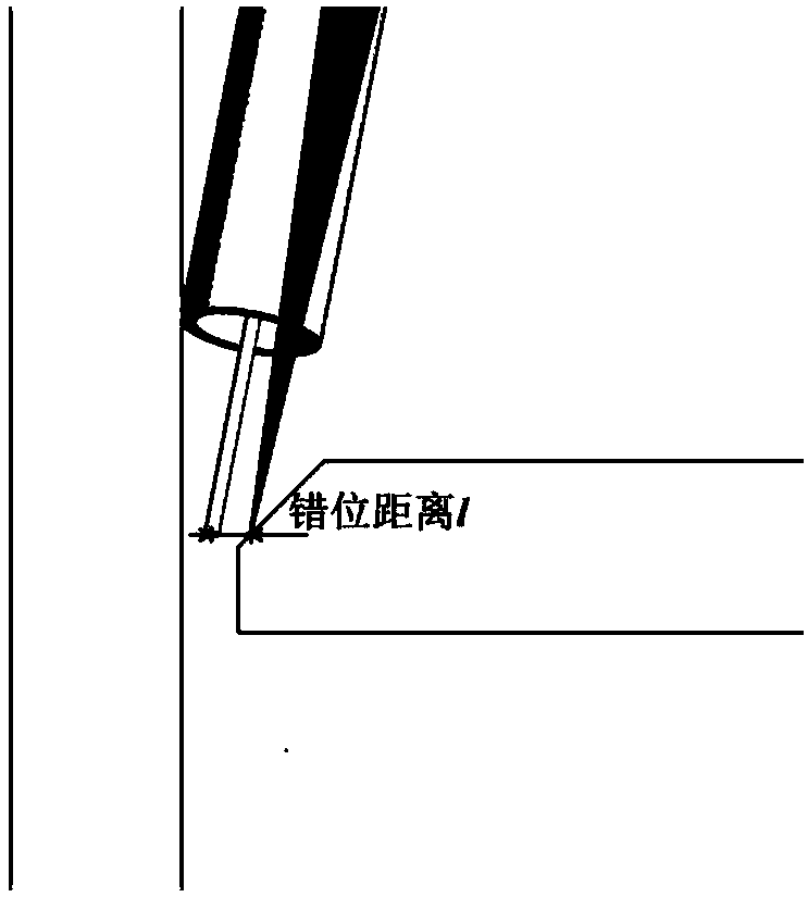
[0050] Embodiment 3: The difference between this embodiment and Embodiment 1 is that the laser beam and the tip of the welding wire are staggered along the direction perpendicular to the weld seam, which means that the plane swept by the laser beam along the moving direction and the plane swept by the welding wire along the moving direction The planes are staggered along the direction perpendicular to the weld. Others are the same as in the first embodiment.


PUM

PropertyMeasurementUnit
thicknessaaaaaaaaaa

Abstract

The invention discloses a method for medium-thick plate corner joint light beam-welding wire dislocation laser-MAG composite welding, and relates to the field of material processing engineering. The method solves the problems that in the process of medium-thick plate corner joint laser-MAG composite welding, welding adaptability is poor, surface welding seams are uneven, flatness is poor, back welding seams are not penetrated through smelting, forming is discontinuous, undercutting occurs, whole collapse is caused by excessively high heat input, the welding quality is greatly affected by the assembly precision and the material preparation precision, especially gaps and misalignment; and especially forced welding prototyping on one side of a back vertical plate occurs under the condition that the assembly precision is not high, and the connecting position is not melted to form the whole welding seams. The light beam-welding wire dislocation laser-MAG composite welding method under leading of a laser beam is adopted, and single side welding is conducted to obtain the one-time through-welding and two-sided formed welding seams meeting requirements. By adopting the method, groove afterwelding is reduced, the number of welding beads is decreased, the filling quantity is decreased, the efficiency and the welding speed are obviously improved, and the production cost is reduced.

Description

technical field [0001] The invention relates to a beam-welding wire dislocation laser-MAG composite welding method for corner joints of medium and thick plates, belonging to the field of material processing engineering. Background technique [0002] With the high-speed development of rail trains, ships, and aerospace manufacturing, energy shortages and environmental pollution are becoming more and more serious. High strength, light weight, energy saving, environmental protection and safety have become the inevitable trend and requirements for the development of today's large-scale structural parts manufacturing industry. , so the welding process of structural parts of medium and thick plates has always been a hot research topic for domestic and foreign scholars and large-scale manufacturing enterprises. Corner joints of medium and thick plates are usually made of weathering steel, austenitic and martensitic stainless steel, precipitation hardening stainless steel, high nicke...

Claims


Application Information

Patent Timeline
Patent Type & Authority Patents(China)
IPC IPC(8): B23K26/348
CPCB23K26/348
Inventor 雷正龙吴世博李鹏熊鹰
Owner HARBIN INST OF TECH
Why Eureka
Try Eureka