Method and device for controlling welding hot cracking during welding by performing electromagnetic induction heating

An electromagnetic induction heating and thermal cracking technology, which is applied in welding equipment, welding accessories, manufacturing tools, etc., can solve problems such as weld defects, arcing, and metal softening in the heating zone, so as to reduce the tendency of welding thermal cracks and control welding heat. Cracks, Effect of Temperature Gradient Reduction

Inactive Publication Date: 2012-03-21
CRRC QINGDAO SIFANG CO LTD
View PDF5 Cites 11 Cited by
  • Summary
  • Abstract
  • Description
  • Claims
  • Application Information

AI Technical Summary

Problems solved by technology

For example, the static temperature difference stretching method requires a long heating time to achieve the required temperature difference, which is likely to cause softening of the metal in the heating zone, resulting in low production efficiency and high production costs.
Dynamic temperature difference stretching method, if water spray cooling will pollute the weld pool, resulting in weld defects, affecting the quality of welded joints, and flexible contact cooling with liquid nitrogen will lead to high costs
Rolling method with welding, complex equipment, high manufacturing cost, strict requirements on the shape of the workpiece to be welded, and the rolling wheel is easy to interfere with the welding torch to cause arcing
The impact rolling method with welding is only suitable for thin plate welding, and the energy cannot be precisely controlled, and with the changes in welding specifications and welding materials, the size of the impact rolling wheel needs to be redesigned and prepared

Method used


Image

  • Method and device for controlling welding hot cracking during welding by performing electromagnetic induction heating
  • Method and device for controlling welding hot cracking during welding by performing electromagnetic induction heating
  • Method and device for controlling welding hot cracking during welding by performing electromagnetic induction heating

Examples


Embodiment Construction

[0025] Below in conjunction with accompanying drawing and specific embodiment the present invention is described in further detail:

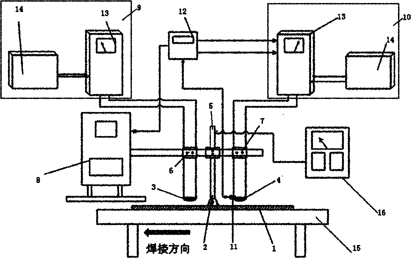
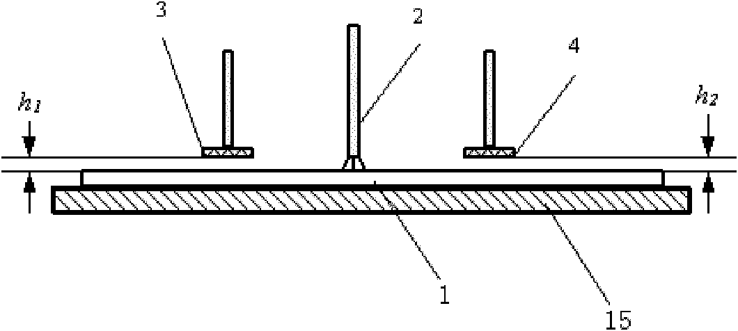
[0026] Such as figure 1 As shown, a device for controlling welding thermal cracks with welding electromagnetic induction heating includes a welding torch 2, a preheating coil 3 is arranged in front of the welding torch 2, a rear heating coil 4 is arranged at the rear of the welding torch 2, the welding torch 2, preheating Both the coil 3 and the post-heating coil 4 are arranged directly above the weld seam, arranged longitudinally along the center line of the weld seam, and the welding torch 2 is connected to a welding power source 16 . During the welding process, the preheating coil 3 first preheats the weld seam of the workpiece 1 to be welded, and then the heating coil 4 heats the weld seam being cooled to achieve the purpose of slow cooling until all welding is completed. This welding method can Reducing the overall or local temperature gra...


PUM

PropertyMeasurementUnit
distanceaaaaaaaaaa
diameteraaaaaaaaaa

Abstract

The invention relates to a method and device for controlling welding hot cracking during welding by performing electromagnetic induction heating. A preheating coil for preheating a workpiece to be welded is arranged in front of a welding gun; an after heating coil for heating a quickly-cooled welding seam for realizing slow cooling is arranged behind the welding gun; and the center of the after heating coil is positioned between positions which are in the center of a welding pool for the workpiece to be welded and are L1 and L2 distances away from corresponding positions of the upper limit temperature T1 and lower limit temperature T2 of the brittleness temperature rang TB of a welding material. In the invention, preheating before welding and slow cooling after welding are realized, so that the strain rate of the welding seam in the brittleness temperature rang is reduced, and welding hot cracking is controlled effectively on the aspects of metallurgy and mechanics; and moreover, the device has a simple structure, high production efficiency and low cost, is easy to realize, and contributes to energy saving and environmental protection.

Description

technical field [0001] The invention relates to a method and a device for controlling welding thermal cracks during welding, in particular to a method and a device for controlling welding thermal cracks by using an electromagnetic induction heating method, and belongs to the field of welding technology. Background technique [0002] Welding hot crack is a common problem in the welding process and is the main defect of welded components. Welding hot cracks mainly refer to the cracks generated when the weld and heat-affected zone metal cool to the high temperature zone near the solidus during the welding process, among which crystal cracks are the most common. Crystalline cracks only exist on the weld, and one is distributed longitudinally on the centerline of the weld, or distributed on both sides of the centerline in an arc shape. These cracks are distributed along the grain boundaries of primary crystallization, especially columnar crystals, crystallization cracks Mainly c...

Claims


Application Information

Patent Timeline
Patent Type & Authority Applications(China)
IPC IPC(8): B23K9/00B23K9/32B23K9/12
Inventor 孟立春刘雪松张亮吕任远方洪渊
Owner CRRC QINGDAO SIFANG CO LTD
Why Eureka
Try Eureka