Automatic hydraulic testing jig

An automatic and test stand technology, which is applied in the field of hydraulic test stands and automatic hydraulic test stands, can solve the problems of inability to test high-load petroleum tools, low safety precautions, and high manual labor intensity, and achieves convenient installation and disassembly. The effect of improving measurement efficiency and increasing the degree of automation

Active Publication Date: 2014-04-02
GUIZHOU GAOFENG GASOLINEEUM MACHINERY
View PDF7 Cites 0 Cited by
  • Summary
  • Abstract
  • Description
  • Claims
  • Application Information

AI Technical Summary

Problems solved by technology

At present, the automatic performance of the hydraulic test stand used for testing petroleum tools is poor, and the manual labor intensity is high. Because of the high hydraulic pressure test, the level of safety precautions is low, and the test load is small, so it is impossible to test high-load petroleum tools.

Method used


Image

  • Automatic hydraulic testing jig
  • Automatic hydraulic testing jig

Examples


Embodiment Construction

[0015] The present invention will be further described in detail below in conjunction with the accompanying drawings and embodiments.

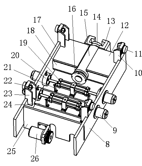
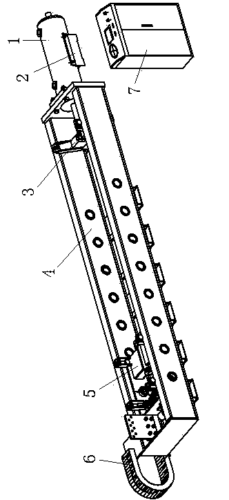
[0016] Example. The present invention as figure 1 shown. An automatic hydraulic test frame, which consists of a hydraulic cylinder 1, a hydraulic cylinder base 2, a movable probe frame 3, a truss 4, a fixed probe frame 5, a drag chain 6, and a console 7; the truss 4 is provided with a movable probe frame 3 and fixed probe frame 5, the movable probe frame 3 is connected with the piston rod of the hydraulic cylinder 1 located at the front end of the truss 4; . The hydraulic cylinder 1 is connected to the electrical and hydraulic control system of the console 7 , the fixed probe frame 5 is connected to the electrical and hydraulic control system of the console 7 , and the bottom of the hydraulic cylinder 1 is provided with a hydraulic cylinder base 2 . The fixed probe frame 5 is as figure 2 As shown, the fixed probe frame 5 includes a...


PUM


Abstract

The invention discloses an automatic hydraulic testing jig which comprises a hydraulic cylinder 1, a hydraulic cylinder base 2, a movable head measuring frame 3, a truss 4, a fixed head measuring frame 5, a drag chain 6 and a control console 7, wherein the movable head measuring frame 3 is connected with the hydraulic cylinder 1 at the front end of the truss 4; and the hydraulic cylinder 1 and the fixed head measuring frame 5 are respectively connected with the control console 7 through an electrical and hydraulic operation system. The test range of the load, the diameter and the length is enlarged; the hydraulic cylinder is used for providing a load applied for the test; the speed of a piston rod can be adjusted; the measured impact force is reduced; the fixed head measuring frame 5 realizes self-traveling and hydraulic inserting and positioning at the truss 4 through a rack and pinion; the test device is controlled by adopting two sets of methods, namely hydraulic and manual and automatic control; and data are acquired, displayed, recorded and printed by configuring a computer-assisted test system; and a panel of the control console 7 is used for displaying a curve graph of the load amplitude, the time, the load and the displacement, thus the measuring efficiency is improved.

Description

technical field [0001] The invention relates to a hydraulic test stand, in particular to an automatic hydraulic test stand, which belongs to the field of test and measurement equipment for downhole petroleum tools. Background technique [0002] Downhole oil tools such as oil drilling tools, jarring tools, fishing tools, accelerators and shock absorbers must be tested for their tensile and pressure properties before going into the well and during maintenance. It is usually necessary to put these tested petroleum tools on a hydraulic test stand for testing. At present, the automatic performance of the hydraulic test stand used for testing petroleum tools is poor, and the manual labor intensity is high. Because of the high hydraulic pressure test, the safety precaution level is low, and the test load is small, so it cannot test high-load petroleum tools. Contents of the invention [0003] The purpose of the present invention is to provide an automatic hydraulic test stand to...

Claims


Application Information

Patent Timeline
Patent Type & Authority Patents(China)
IPC IPC(8): G01M99/00
Inventor 薛桓张亚昌王辉李应虎沈赤卫杨庭华补声军鄢红江张新富成建辉童庆安陈文平李汇平李良群
Owner GUIZHOU GAOFENG GASOLINEEUM MACHINERY
Why Eureka
Try Eureka