Laser head height adjusting device and method based on CCD (charge coupled device) vision

A height adjustment device and height adjustment technology, used in laser welding equipment, welding equipment, metal processing equipment, etc., can solve the problems of decreased welding or cutting accuracy, differences, changes, etc.

Active Publication Date: 2013-03-13
INST OF SEMICONDUCTORS - CHINESE ACAD OF SCI
View PDF7 Cites 16 Cited by
  • Summary
  • Abstract
  • Description
  • Claims
  • Application Information

AI Technical Summary

Problems solved by technology

[0002] When using a laser to process a workpiece, the position of the laser spot is generally determined by a helium-neon laser, especially when welding or cutting a larger workpiece, such as tailor welding of a large plate, because the plate surface cannot be guaranteed to be flat, which will cause laser During the welding process, the defocus of laser welding parameters changes, which requires the operator to measure the height of the laser head after a period of time, so as to prevent a large change in the defocus, which will deteriorate the welding performance and make the processed The workpiece does not meet the requirements. At present, a ruler is used to measure the distance between the workpiece and the lens to calculate the defocus amount. This is a large workload, and there are also large differences between multiple measurements, resulting in welding or cutting. Decreased precision greatly affects welding or cutting quality

Method used


Image

  • Laser head height adjusting device and method based on CCD (charge coupled device) vision
  • Laser head height adjusting device and method based on CCD (charge coupled device) vision

Examples


Embodiment Construction

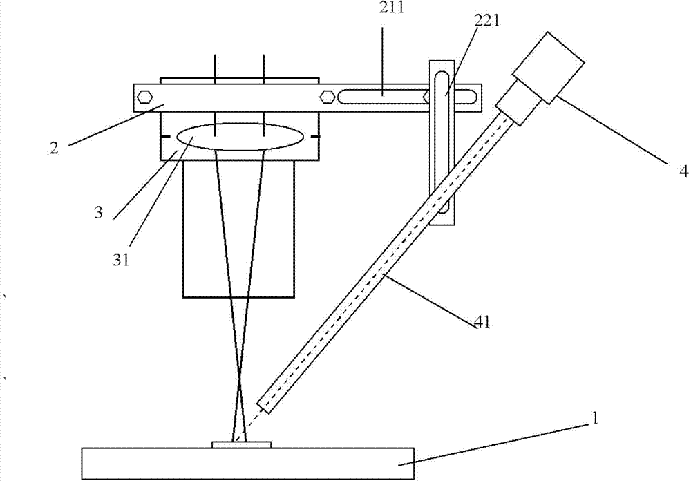
[0019] see figure 1 As shown, the present invention provides a kind of laser head height adjustment device based on CCD vision, comprising:

[0020] A processing platform 1;

[0021] A clamping device 2, which is located above the processing platform 1, the clamping device 2 includes a transverse clamping connection part 21 and a longitudinal clamping connection part 22, and the horizontal clamping connection part 21 and the longitudinal clamping connection part 22 are pivoted to each other Then, there is a transverse sliding groove 211 on the transverse clamping connection part 21 of the clamping device 2, which facilitates the sliding of the longitudinal clamping connection part 22 of the clamping device 2, and there is a longitudinal clamping connection part 22 on the clamping device 2 The longitudinal chute 221 is convenient for the CCD camera 4 pivotally connected to the longitudinal clamping connection part 22 of the clamping device 2 to slide and adjust the angle;

[...


PUM

PropertyMeasurementUnit
diameteraaaaaaaaaa

Abstract

The invention relates to a laser head height adjusting device and a laser head height adjusting method based on CCD (charge coupled device) vision. The laser head height adjusting device based on CCD vision comprises a machining platform, a clamping device, a laser head and a CCD camera, wherein the clamping device is arranged above the machining platform and comprises a transverse clamping connecting part and a longitudinal clamping connecting part which are mutually pivoted; the laser head is arranged on the pivoted transverse clamping connecting part of the clamping device and is arranged above the machining platform; and the CCD camera is pivoted on the pivoted longitudinal clamping connecting part of the clamping device, and the angle between the CCD camera and the longitudinal clamping connecting part is adjustable. The laser head height adjusting device and the laser head height adjusting method based on CCD vision have the advantages that the laser machining quality can be guaranteed, the machining accuracy is improved and the situation of position change of a focal point can be determined rapidly and conveniently.

Description

technical field [0001] The invention relates to a laser-assisted processing method, in particular to a CCD vision-based laser head height adjustment device and adjustment method. Background technique [0002] When using a laser to process a workpiece, the position of the laser spot is generally determined by a helium-neon laser, especially when welding or cutting a larger workpiece, such as tailor welding of a large plate, because the plate surface cannot be guaranteed to be flat, which will cause laser During the welding process, the defocus of laser welding parameters changes, which requires the operator to measure the height of the laser head after a period of time, so as to prevent a large change in the defocus, which will deteriorate the welding performance and make the processed The workpiece does not meet the requirements. At present, a ruler is used to measure the distance between the workpiece and the lens to calculate the defocus amount. This is a large workload, a...

Claims


Application Information

Patent Timeline
Patent Type & Authority Applications(China)
IPC IPC(8): B23K26/04B23K26/42B23K26/046B23K26/70
Inventor 赵伟芳林学春于海娟李晋闽
Owner INST OF SEMICONDUCTORS - CHINESE ACAD OF SCI
Why Eureka
Try Eureka