Hierarchical monitoring system

A monitoring system and hierarchical technology, applied in the field of electronic information, can solve the problems of high construction cost and construction difficulty of network monitoring, and achieve the effect of not affecting the decoration effect, reducing construction difficulty, and no equipment occupying space.

Inactive Publication Date: 2019-03-19
沈阳安网信息技术有限公司
View PDF0 Cites 9 Cited by
  • Summary
  • Abstract
  • Description
  • Claims
  • Application Information

AI Technical Summary

Problems solved by technology

[0010] The purpose of the present invention is to solve the problem of high construction cost and difficult construction of network monitoring, and at the same time solve the problem that other related system equipment has no interface to connect to the network during the wiring process, and provides a kind of other equipment for Ethernet data exchange through the access of monitoring cameras Applied Solutions

Method used


Image

  • Hierarchical monitoring system
  • Hierarchical monitoring system
  • Hierarchical monitoring system

Examples


Embodiment 1

[0038] The purpose of this embodiment is to solve the problem of high construction cost and difficult construction of network monitoring, and at the same time solve the problem of no interface connection of other related system equipment in the wiring process, and provide a kind of other equipment for monitoring camera access to carry out Ethernet data Solutions for swap applications.

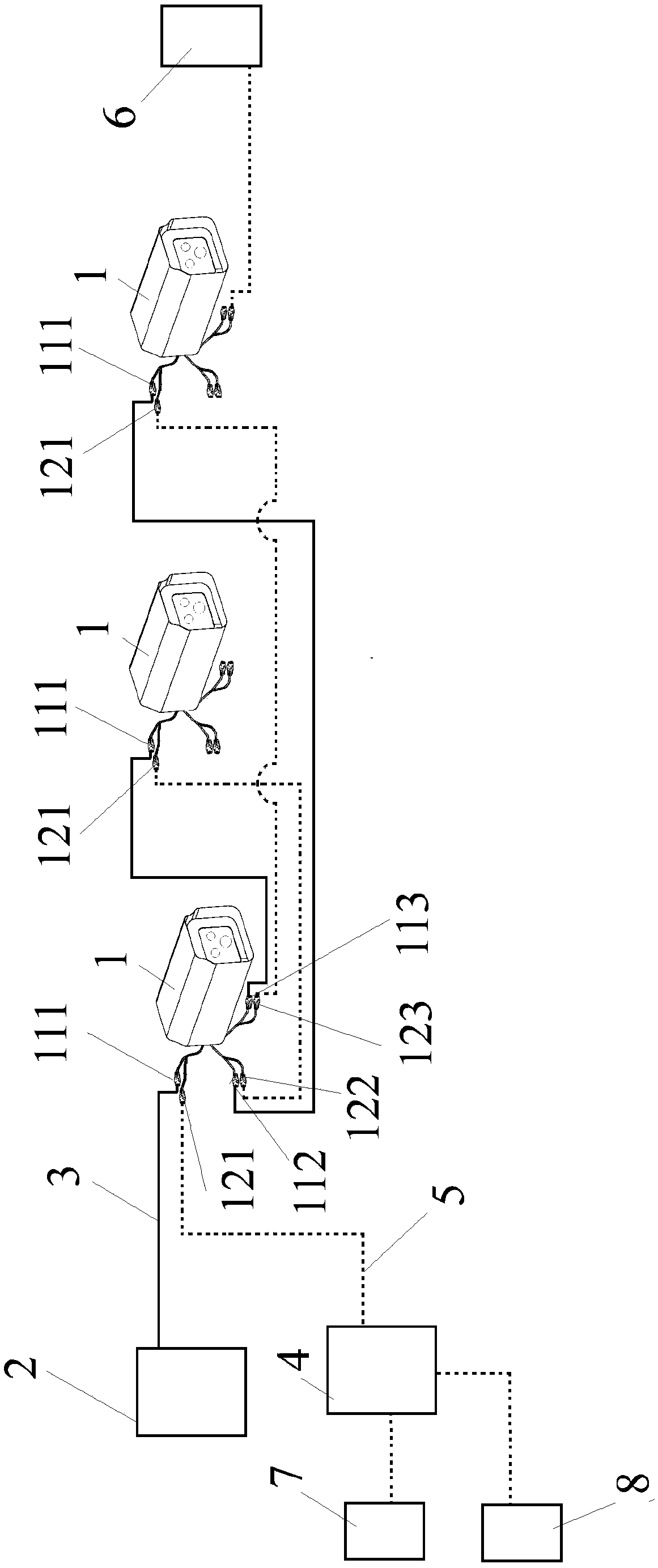
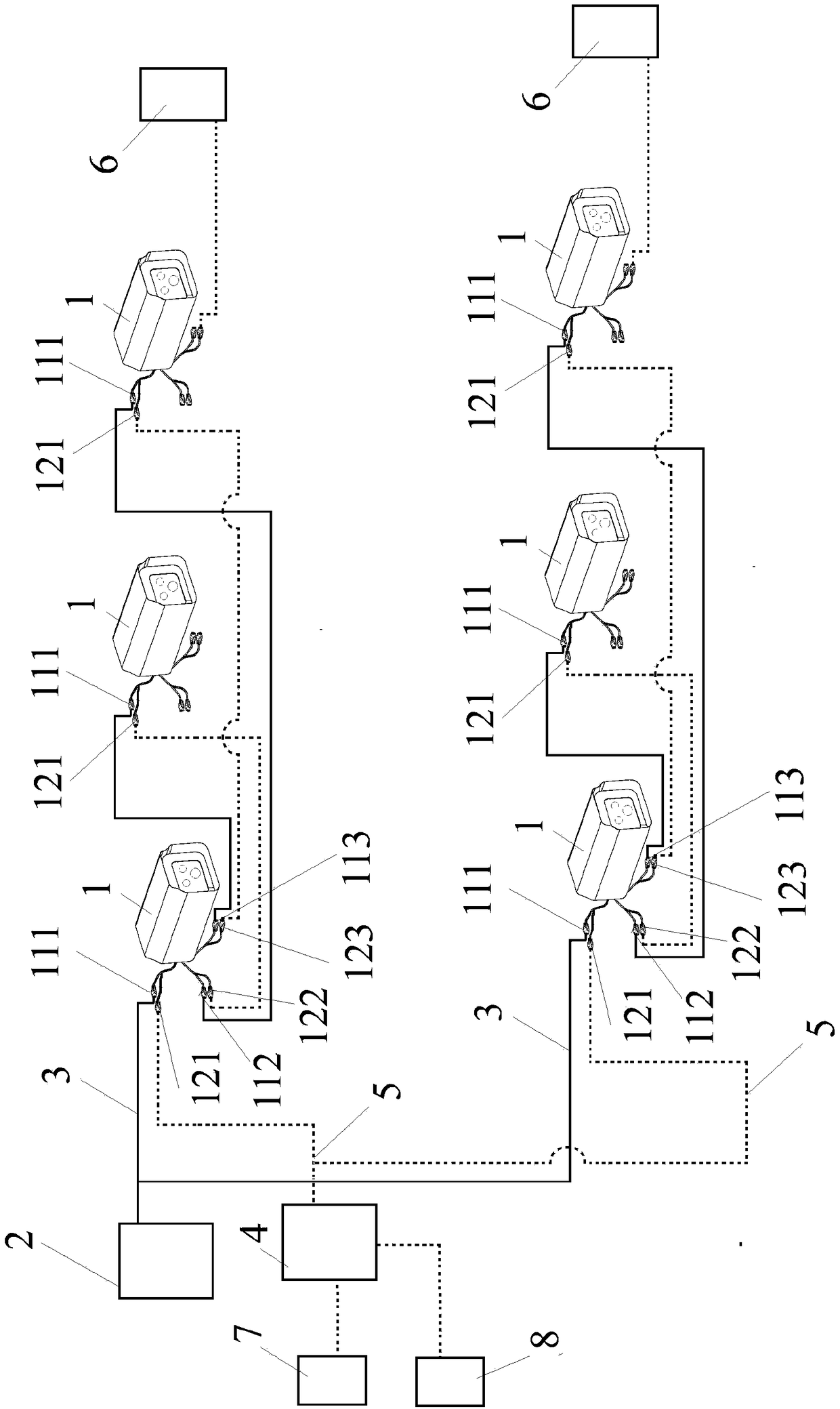
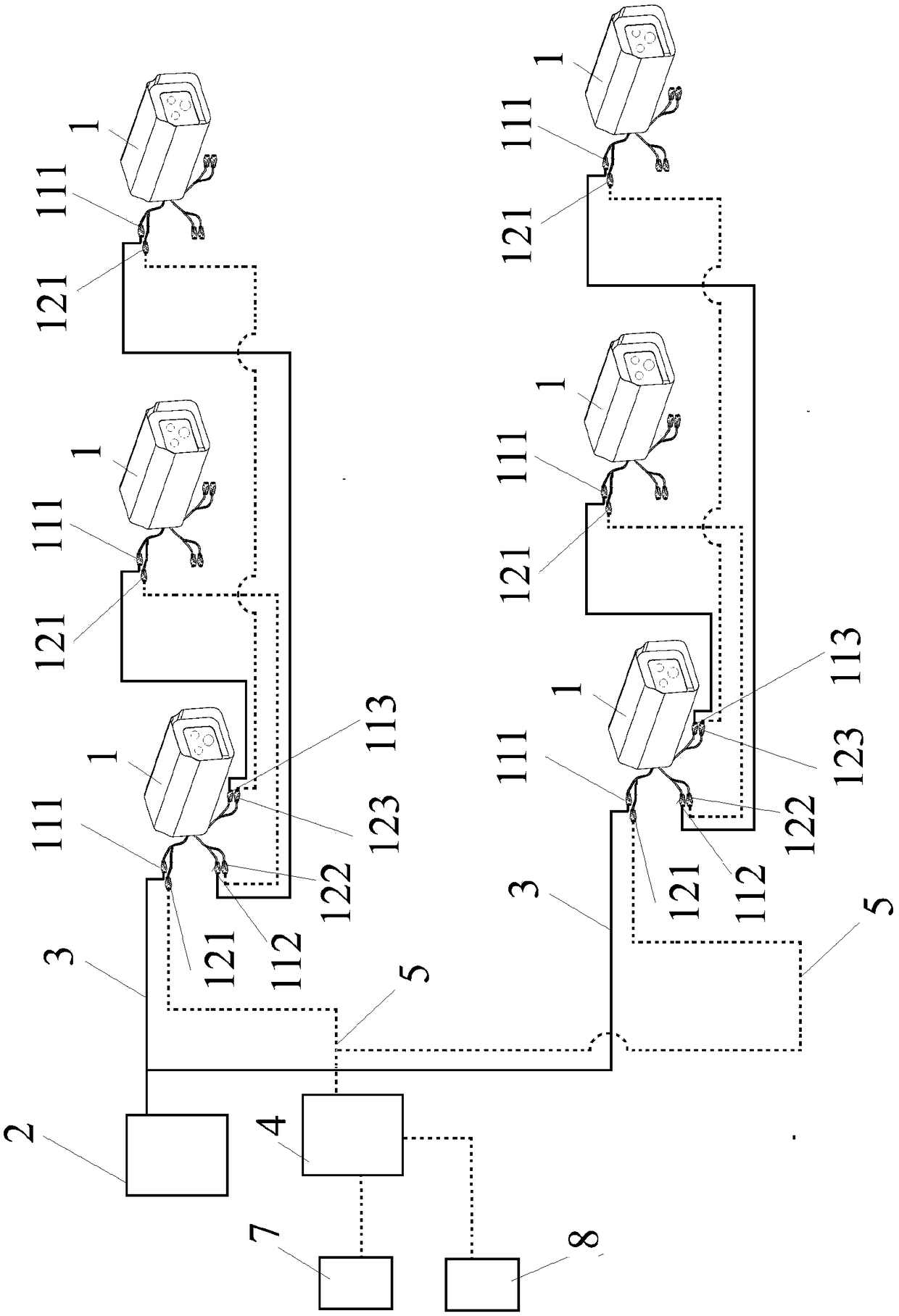
[0039]This embodiment specifically provides a hierarchical monitoring system, the power supply 2 is connected to the first power port 111 of the first network camera 1 through the power cord 3, the second power port 112 and the third power port of the first network camera 1 113 is respectively connected to the first power port 111 of the second network camera 1 and the first power port 111 of the third network camera 1 .

[0040] The monitoring center network switch 4 is connected to the first network interface 121 of the first network camera 1 through the network cable 5, and the third network...

Embodiment 2

[0059] In this embodiment, only one group of network cameras is used, and network accessory terminals are arranged, and the rest of the implementation methods and expected effects are the same as in Embodiment 1.

Embodiment 3

[0061] In this embodiment, the network cameras are used in groups, but no network accessory terminals are arranged, and the remaining implementation methods and expected effects are the same as in Embodiment 1.


PUM


Abstract

The invention discloses a hierarchical monitoring system. A power supply is connected to the first power supply port of the first network camera through a power line. The second power supply port andthe third power supply port of the first network camera are respectively connected to the first power supply port of the second network camera and the first power supply port of the third network camera. A monitoring center network switch is connected to the first network interface of the first network camera through a network line. The third network interface and the second network interface of the first network camera are respectively connected to the first network interface of the second network camera and the first network interface of the third network camera. The second network interfaceand / or the third network interface are electrically connected to a network accessory terminal. The monitoring center network switch is separately connected to a manager video monitor and a manager console. The network accessory terminal comprises at least a entrance guard, a microphone, a iris recognition device, a face recognition device, an intrusion alarm system, a network hard disk recorder,a network alarm and a network interphone.

Description

technical field [0001] The invention relates to the technical field of electronic information technology, and in particular provides a hierarchical monitoring system. Background technique [0002] For the installation of monitoring system engineering, the first difficulty lies in the wiring. If there are too many wires, it is necessary to install trough bridges and metal wire slots. Not only is the construction more difficult, but it also takes up most of the system deployment cost; Checking and wiring and subsequent repairs and maintenance also caused a lot of trouble; a good set of wiring will play a vital role in ensuring the normal and lasting operation of the entire system, and 85% of the faults in the project are caused by the wiring. If the construction of complex lines can be simplified, the number of lines can be changed to less, and the equipment can also be changed from more to less, and even the application of some equipment can be reduced, which may become the u...

Claims


Application Information

Patent Timeline
Patent Type & Authority Applications(China)
IPC IPC(8): H04N7/18H04N5/907H04N5/247G08B21/18
CPCH04N5/907H04N7/181H04N7/186G08B21/182H04N23/90
Inventor 李林伟
Owner 沈阳安网信息技术有限公司
Why Eureka
Try Eureka