Mechanical-electrical integrated electronic lock body
What is AI technical title?
AI technical title is built by Patsnap AI team. It summarizes the technical point description of the patent document.
An electronic lock and lock body technology, applied in the field of locks, can solve the problems of troublesome assembly, disassembly and maintenance, not economical and applicable, complex structure, etc., and achieve the effects of convenience, reliability, simple structure, and compact structure connection.
Inactive Publication Date: 2013-03-13
刘茂胜
View PDF5 Cites 23 Cited by
Summary
Abstract
Description
Claims
Application Information
AI Technical Summary
This helps you quickly interpret patents by identifying the three key elements:
Problems solved by technology
Method used
Benefits of technology
Problems solved by technology
[0007] The present invention proposes a simple and compact structure in order to solve the existing electronic lock body complex structure, poor strength, large volume, generally thicker and wider lock body, relatively t
Method used
Image
Click on the blue label to locate the original text in one second.
Reading with bidirectional positioning of images and text.
Examples
Embodiment 1
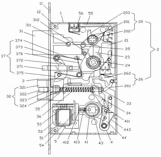
[0121] Such as Figures 1 to 12 As shown, the electromechanical integrated electronic lock body of the present invention includes a lock housing 1 and a mechanical drive mechanism 2 , a locking mechanism 3 , a deadbolt actuator 4 and an electronically controlled drive mechanism 5 disposed in the lock housing 1 .
[0122] The lock housing 1 is used to carry the mechanical driving mechanism 2, the locking mechanism 3, the bolt actuator 4 and the electric control driving mechanism 5. The lock housing 1 is roughly rectangular, and one side is provided with a side trim 11. Both ends are provided with U-shaped connecting plates 12 for assembly.
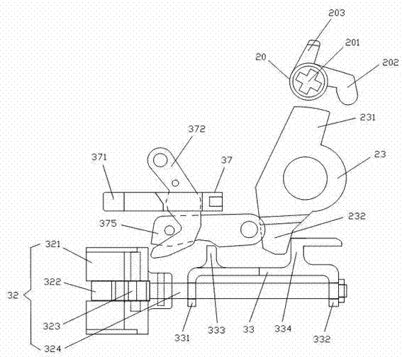
[0123] The mechanical drive mechanism 2 includes a key toggle 20, a gear plate 21, a gear seat 22, a drive plate 23, a deadbolt toggle 24, a main lock tongue spring 25 and a positive turning throw 26.
[0124] The key toggle 20 is located on one side of the drive plate 23, and includes a key socket 201, a transmission end 202 and a contact...
Embodiment 2
[0150] Such as figure 2 and Figures 13 to 15 As shown, Embodiment 2 of the present invention is the same as Embodiment 1, and also includes a lock case 1 and a mechanical drive mechanism 2 , a locking mechanism 3 , a bolt actuator 4 and an electric drive mechanism 5 disposed in the lock case 1 .
[0151] Compared with Embodiment 1, the electromechanical integrated electronic lock body of Embodiment 2 of the present invention differs in that:
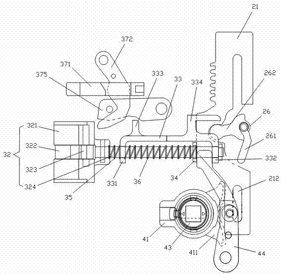
[0152] The mechanical driving mechanism 2 of Embodiment 2 of the present invention includes a key toggle 20, a gear plate 21, a gear seat 22, a drive plate 23, a bolt toggle 24 and a main bolt spring 25, wherein the The gear plate 21 is roughly rectangular, with two guide slots 212 respectively, one side of which is provided with teeth, and the other side is provided with a U-shaped slot 213 .
[0153] The deadbolt actuator 4 of Embodiment 2 of the present invention includes a clutch seat 41, an outer shift fork 42, an inner shift fo...
PUM
Property
Measurement
Unit
Thickness
aaaaa
aaaaa
Thickness
aaaaa
aaaaa
Abstract
The invention relates to a mechanical-electrical integrated electronic lock body which comprises a lock shell, a mechanical driving mechanism, a locking mechanism, a spring bolt executing mechanism and an electronic control driving mechanism, wherein the mechanical driving mechanism comprises a key stirring rod, a gear plate, a gear seat and a spring bolt stirring rod; the key stirring rod rotates to drive the gear plate to move and enable the gear seat and the spring bolt stirring rod to rotate; the locking mechanism comprises a spring bolt, an inclined bolt and an inclined bolt linkage rod; the spring bolt stirring rod drives the main spring bolt to move; the inclined bolt linkage rod drives the inclined bolt to move; the spring bolt executing mechanism comprises a clutch seat, a stirring rod, an inner shifting fork and an outer shifting fork; the clutch seat drives the inner shifting fork to rotate by a clutch pin and drives the stirring rod to swing; the electronic control driving mechanism is driven by a motor and transmitted by an eccentric wheel; and the clutch pin is pushed by a push frame. The spring bolt executing mechanism can be additionally provided with a clutch seat plate to make the clutch seat plate keep in touch with the gear plate and drive the gear plate to move. The mechanical-electrical integrated electronic lock body is small in size, thin, narrow, simple to operate, high in reliability of electro-mechanical transformation, and strong in theft guard.
Description
technical field [0001] The invention relates to a lock, in particular to a mechanical and electrical integrated electronic lock body. Background technique [0002] The current anti-theft lock body is divided into a full mechanical anti-theft lock body and an electronic intelligent anti-theft lock body. Fully mechanical anti-theft locks are becoming less and less suitable for modern people's life characteristics due to the inconvenience of locking the door, and have been gradually replaced by electronic anti-theft locks; however, the original electronic lock body is generally thick, wide and large Meet the installation requirements of some anti-theft doors (especially thin doors), and at the same time cause greater damage to the door; therefore, how to design a simple structure, low cost, high strength, high reliability of mechatronic conversion, and low failure rate, An electronic lock that is convenient to use, safe and reliable, smaller in size, thinner in thickness, narr...
Claims
Application Information
Patent Timeline
Application Date:The date an application was filed.
Publication Date:The date a patent or application was officially published.
First Publication Date:The earliest publication date of a patent with the same application number.
Issue Date:Publication date of the patent grant document.
PCT Entry Date:The Entry date of PCT National Phase.
Estimated Expiry Date:The statutory expiry date of a patent right according to the Patent Law, and it is the longest term of protection that the patent right can achieve without the termination of the patent right due to other reasons(Term extension factor has been taken into account ).
Invalid Date:Actual expiry date is based on effective date or publication date of legal transaction data of invalid patent.

