Permanent magnet coupler for belt driving

A technology of belt drive and coupling, which is applied in the direction of permanent magnet clutch/brake, transmission device, belt/chain/gear, etc. It can solve the problems of affecting the service life of the motor, shortening the service life of the belt, and reducing the service life of the motor, so as to improve the The motor power is reasonable, the effect of improving power utilization and prolonging the service life

Active Publication Date: 2013-03-13
上海曜中能源科技有限公司
View PDF5 Cites 6 Cited by
  • Summary
  • Abstract
  • Description
  • Claims
  • Application Information

AI Technical Summary

Problems solved by technology

[0004] 1. The traditional motor adopts a hard start method. The large current at start-up has a large impact on the grid, which affects the quality of power supply of the grid; damages the motor insulation and reduces the life of the motor; produces a large impact on the motor stator coil and rotor squirrel cage, It will cause the motor to be tight, the coil to be deformed, and the squirrel cage to be broken, etc.
[0005] 2. When the motor is started, the tension on the belt suddenly increases, which shortens the service life of the belt
[0006] 3. There is a usual mechanical connection between the motor and the load, so the vibration of t

Method used


Image

  • Permanent magnet coupler for belt driving
  • Permanent magnet coupler for belt driving
  • Permanent magnet coupler for belt driving

Examples


Example Embodiment

[0043] The present invention will be further described in detail below with reference to the accompanying drawings and specific embodiments, so that those skilled in the art can more clearly understand other advantages and effects of the present invention.

[0044] It should be noted that the structures, proportions, sizes, etc. shown in the accompanying drawings of the specification are only used to cooperate with the specific embodiments, so that those skilled in the art can understand the concept of the present invention more clearly, and are not used to limit the protection scope of the present invention. . Any structural modification, proportional relationship change, or size adjustment should still fall within the protection scope of the present invention without affecting the efficacy and purpose of the present invention. For ease of description, the relative positional relationship of each component is described according to the layout of the drawings in the specification...


PUM


Abstract

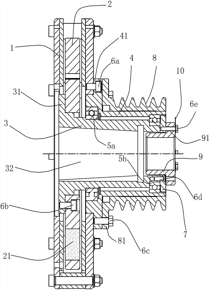
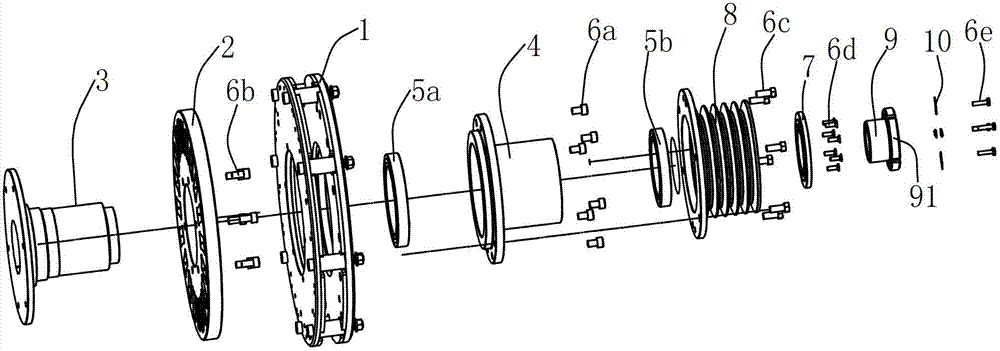
The invention discloses a permanent magnet coupler for belt driving. The permanent magnet coupler comprises a conductor rotor, a permanent magnet rotor, a belt pulley, an input shaft sleeve and an output bearing block, wherein the permanent magnet rotor is fixed on an outer cylindrical surface of the input shaft sleeve; the belt pulley is fixed on an outer cylindrical surface of the output bearing block; and the output bearing block is fixedly connected with the conductor rotor, and supported on the outer cylindrical surface of the input shaft sleeve through a bearing. The permanent magnet coupler disclosed by the invention has a soft starting function, better damping performance, can increase the utilization rate of motor power and bear a greater load, and has a more compact structure and excellent axial rigidity.

Description

technical field [0001] The invention relates to a permanent magnet coupler, in particular to a permanent magnet coupler device for belt transmission. Background technique [0002] The traditional belt drive is mainly composed of a motor, a belt and a load. Pulleys are installed at the output end of the motor and the input end of the load, and the output of the motor is transmitted to the load through the connection between the belt and the pulley. Belt transmission has the following characteristics: 1) Simple structure, suitable for transmission occasions with a large center distance between two shafts; 2) Smooth transmission without noise, capable of buffering and absorbing vibration; 3) When overloaded, the belt will slip on the pulley to prevent The weak parts are damaged and play a protective role, so they are widely used. [0003] However, there are many problems in the traditional belt connection transmission, which are mainly reflected in the following aspects: [0...

Claims


Application Information

Patent Timeline
IPC IPC(8): F16H49/00H02K49/04H02K49/10
Inventor 黄晓兵杜毅
Owner 上海曜中能源科技有限公司
Why Eureka
Try Eureka