

Sealing valve with double valve plates
A technology of sealing valve and double valve plate, which is applied in the direction of lifting valve, valve details, valve device, etc., can solve the problems of dangerous working environment for operators, complicated operation, complicated mechanism, etc., and achieve good closing effect, simple valve structure, and tight sealing good effect
- Summary
- Abstract
- Description
- Claims
- Application Information
AI Technical Summary
Problems solved by technology
Method used
Image

Examples
Embodiment 1
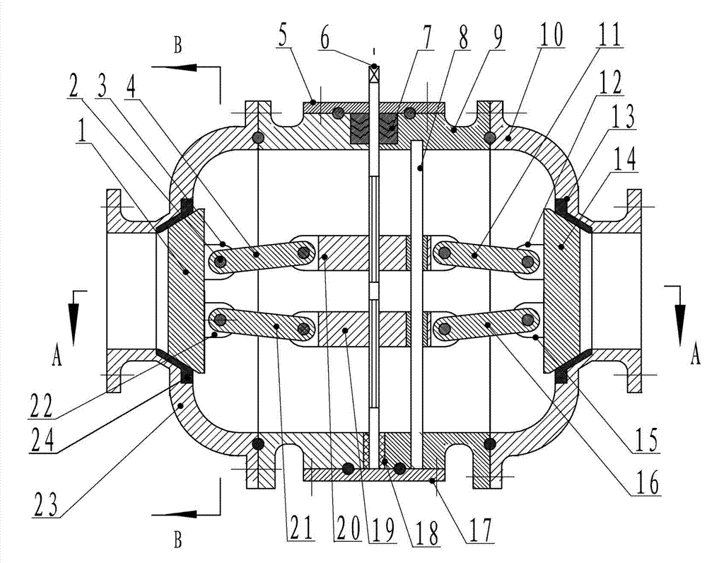
[0035] Example 1 (see Figure 1-4):
[0036] The valve plate in Example 1 is a cone-shaped valve plate.
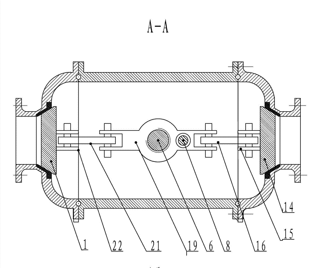
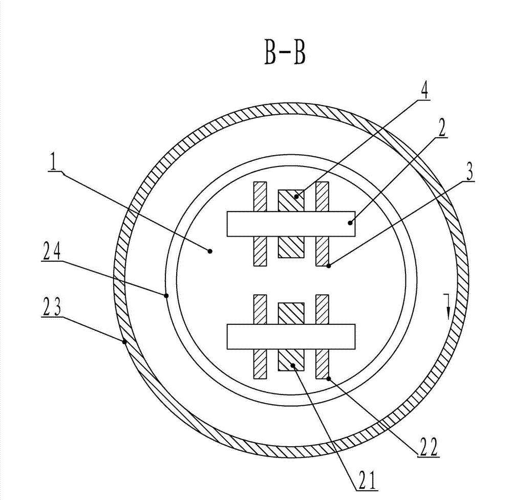
[0037] This embodiment includes left valve body 23, middle valve body 9, right valve body 10, left valve plate 1, right valve plate 14 and valve plate linkage mechanism; 9 sealing connection; a sealing ring is provided between the left valve plate 1 and the right valve plate 14 and the medium inlet and outlet on the left and right valve bodies; the valve plate linkage mechanism is hinged with the left valve plate and the right valve plate respectively.
[0038] The valve plate linkage mechanism is composed of the first upper connecting frame 20, the lower connecting frame 19, the first guide rod 8, the first connecting plate 4 to the fourth connecting plate 21 which are threadedly connected by the leading screw 6 and the leading screw 6; The lower end of described leading screw 6 is fixedly connected with the lower wall of middle valve body 9 by axle sleeve 18, and its upp...
Embodiment 2
[0047] Example 2 (see Figure 5, Figure 6, Figure 1, Figure 4):
[0048] Embodiment 2 is suitable for valves with larger diameters. The difference between embodiment 2 and embodiment 1 is the left and right conical valve plate linkage mechanism. The left and right conical valve plate linkage mechanism of embodiment 2 consists of screw 6, and The second lower connecting frame 31, the second upper connecting frame, the second guide bar 30 to the fifth guide bar 38, and the fifth to twelfth connecting plates that are threadedly connected by the lead screw 6 are composed; the lower end of the lead screw 6 passes through the shaft Cover 18 is fixedly connected with the lower wall of middle valve body 9, and its upper end stretches out the upper wall of middle valve body 9, is provided with sealing ring 7 at the top of the contact position of the upper wall of middle valve body 9 and leading screw 6; The threads of the upper and lower parts of the lead screw 6 are forward and reverse...
PUM
 Abstract
Description
Claims
Application Information