
A detection circuit of a display panel

A display panel and detection circuit technology, applied to static indicators, instruments, etc., can solve the problem of adding laser cutting technology

Active Publication Date: 2013-03-13
AU OPTRONICS KUNSHAN CO LTD
View PDF5 Cites 10 Cited by
  • Summary
  • Abstract
  • Description
  • Claims
  • Application Information

AI Technical Summary

Problems solved by technology

Next, after the display panel is detected, the detection circuit wiring is cut off by using a laser cutting process, but the detection procedure needs to increase the laser cutting process

Method used


Image

  • A detection circuit of a display panel
  • A detection circuit of a display panel
  • A detection circuit of a display panel

Examples


Embodiment Construction

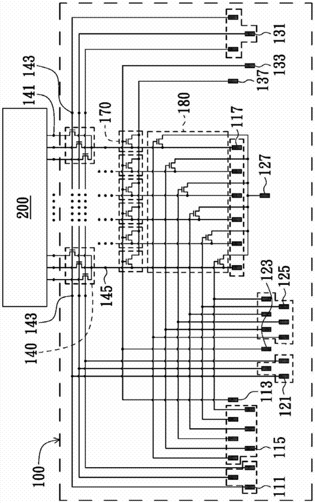
[0038] Please refer to figure 1 , figure 1 It is a detailed schematic diagram of the detection circuit of the first embodiment of the present invention. Such as figure 1 As shown, the detection circuit 100 of the embodiment of the present invention is electrically connected to the display panel 200 . The detection circuit 100 includes a first test part (composed of a plurality of first switching terminals 111, a first enabling terminal 113, a plurality of first control terminals 115 and a plurality of first data terminals 117), a second Two test sections (composed of multiple second switching terminals 121, a second enabling terminal 123, multiple second control terminals 125, and a second data terminal 127), third testing sections (composed of multiple third switching terminals terminal 131 , a third enable terminal 133 and a third data terminal 137 ), a plurality of first multiplexers 140 , a plurality of first switch units 170 and a second multiplexer 180 . In this figu...


PUM


Abstract

The invention provides a detection circuit of a display panel. The detection circuit comprises a first test part, a second test part, a third test part, a plurality of multiplexers, a plurality of first switch units and a second multiplexer. The first test part, the second test part and the third test part are electrically connected with the plurality of multiplexers. The output ends of the multiplexers are electrically connected to a plurality of data lines of the display panel. The first multiplexers, the first switch units and / or the second multiplexer are enabled respectively, so that the first test part, the second part or the third part can output a detection signal to the display panel selectively for a detection process.

Description

technical field [0001] The invention relates to a detection circuit, in particular to a detection circuit of a display panel. Background technique [0002] In the current manufacturing process of a display panel, a test procedure is used to test whether the driving circuit of each pixel in the array substrate of the display panel operates correctly. For example, circuit wiring for detection is provided around the driving circuit. Generally speaking, there are two types of short-ring layout and shorting-bar layout. . [0003] The detection procedure mainly uses the detection signal to be input to the driving circuit through the detection circuit wiring, so as to drive each pixel in the display panel for testing. Next, after the display panel is inspected, the inspection circuit wiring is cut by using a laser cutting process, but the inspection procedure requires an additional laser cutting process. Contents of the invention [0004] The present invention proposes a detec...

Claims


Application Information

Patent Timeline
IPC IPC(8): G09G3/00
Inventor 林男颖丁友信傅春霖徐伟钧陈沛桦
Owner AU OPTRONICS KUNSHAN CO LTD
Learn More