An optical fiber network system and a method for asynchronous communication data transmission using the system

An optical fiber network, optical communication module technology, applied in the direction of optical fiber transmission, etc., can solve the problems of information error, abnormal pulse width deviation of data logic level signal, bit error and so on

Inactive Publication Date: 2015-08-19
深圳市开锐光通信技术有限公司 +1
View PDF4 Cites 0 Cited by
  • Summary
  • Abstract
  • Description
  • Claims
  • Application Information

AI Technical Summary

Problems solved by technology

Due to the tailing phenomenon of the optical transmitting unit of the optical transmitting module, the binary logic high level signal in the transmitted data will inevitably have a pulse width change after being transmitted by the optical receiving module and the optical transmitting module. If the above-mentioned asynchronous communication data is used directly In the way of transmission on the multi-stage optical fiber node ring, the pulse width will change once every time the data logic level signal is transmitted to a group of optical receiving modules and optical transmitting modules. After passing through a certain number of optical receiving modules and optical transmitting modules, the data logic There will be a large deviation in the pulse width of the level signal, which will easily lead to bit errors and even information errors

Method used


Image

  • An optical fiber network system and a method for asynchronous communication data transmission using the system
  • An optical fiber network system and a method for asynchronous communication data transmission using the system
  • An optical fiber network system and a method for asynchronous communication data transmission using the system

Examples


Embodiment Construction

[0021] This embodiment is a preferred implementation mode of the present invention, and other principles and basic structures that are the same or similar to this embodiment are within the protection scope of the present invention.

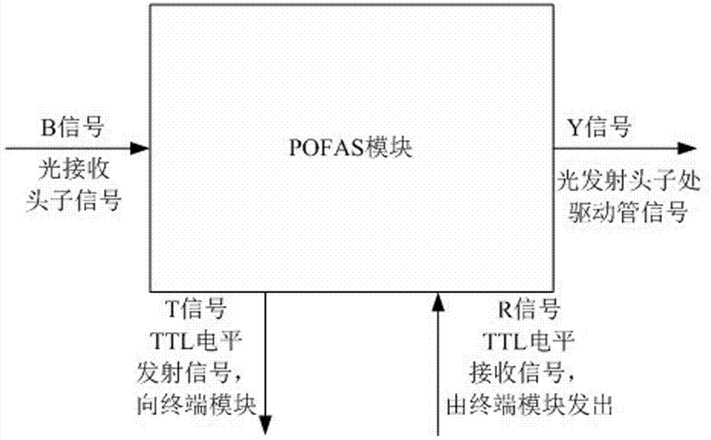
[0022] Please see attached figure 1 , in the present invention, the receiving signal of the optical communication module is called the B signal, the sending signal of the optical communication module is called the Y (drive tube) signal, and the signal sent to the terminal equipment (such as an electric meter) is called the T signal. A signal sent by a terminal device (such as an electric meter) is called an R signal. In this embodiment, the working mode of the optical communication module itself is defined as: sending to a terminal device (such as an electric meter) one way, the T signal is equal to the B signal or the reverse signal of the T signal equal to the B signal; sending to the next-level terminal device (such as Meter) all the way, in t...


PUM


Abstract

The invention discloses an optical fiber network system and a method for performing asynchronous communication data transmission by the system. The system comprises a local side device and more than one terminal device, the local side device and each terminal device are connected through optical fibers to form a single loop or double loop serial optical fiber network, the local side device and each terminal device are respectively connected with optical communication modules, each optical communication module is provided with one or two optical receiving terminals and one or two optical sending terminals, and the optical fibers are connected with the optical receiving terminals and the optical sending terminals. The optical communication modules in the terminal devices negate a received data signal and then send the signal to next terminal device. According to the novel optical fiber network system and the method for performing the asynchronous communication data transmission by the system, the problem of error code during data transmission by the asynchronous communication in an electric power telecommunication system is solved, the key issue of asynchronous data transmission during electric power optical fiber communication is solved, and the development of an electric power optical fiber high speed communication network is facilitated.

Description

technical field [0001] The invention discloses an optical fiber network system and a data transmission method, in particular an optical fiber network system and a method for asynchronous communication data transmission using the system. Background technique [0002] With the development of optical fiber technology, optical fiber transmission technology is more and more widely used in people's daily life. At present, in the power optical fiber Terminal devices (such as electric meters) are serially connected through optical modules and optical fibers to form a loop to form an optical fiber network system. The central office equipment (such as a concentrator) and each terminal equipment (such as an electric meter) are equipped with an optical sending module and an optical receiving module. During communication, the command data of asynchronous communication is sent from the central device), the optical signal is transmitted by the optical fiber to the optical receivin...

Claims


Application Information

Patent Timeline
Patent Type & Authority Patents(China)
IPC IPC(8): H04B10/25
Inventor 彭斌张志方
Owner 深圳市开锐光通信技术有限公司
Why Eureka
Try Eureka