Self-locking locking mechanism

A locking mechanism, self-locking technology

Inactive Publication Date: 2014-12-17
LIAONING UNIVERSITY OF TECHNOLOGY +1
View PDF4 Cites 2 Cited by
  • Summary
  • Abstract
  • Description
  • Claims
  • Application Information

AI Technical Summary

Problems solved by technology

However, the existing locking mechanism has the following disadvantages: 1. The locking mechanism is complicated in structure and difficult to process and control; 2. The contact surface between the locking mechanism and the piston rod of the clamping cylinder is semicircular or rectangular, resulting in insufficient force on the piston rod. Uniform and large stress, which seriously affects the locking effect; 3. The clamping system needs continuous high-pressure oil to ensure the locking state of the locking mechanism during the process of clamping and maintaining pressure, which increases energy consumption. Under the condition, it is easy to lock failure, resulting in serious consequences

Method used


Image

  • Self-locking locking mechanism
  • Self-locking locking mechanism
  • Self-locking locking mechanism

Examples


Embodiment Construction

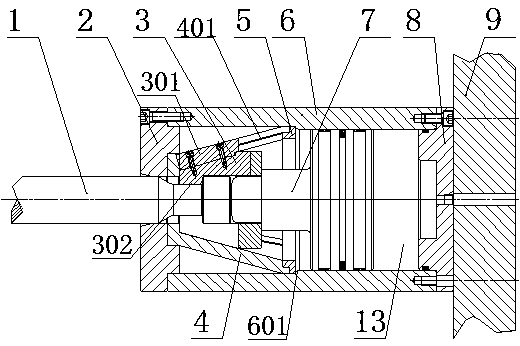
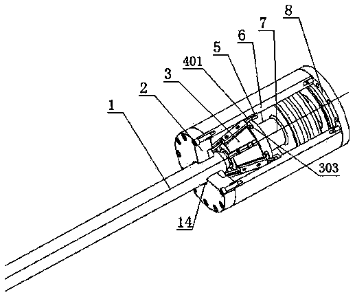
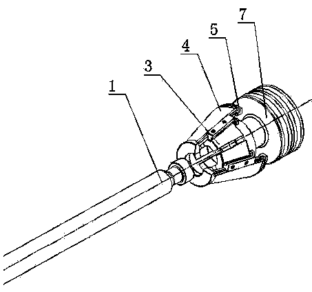
[0023] As shown in the figure, the self-locking locking mechanism includes a cylinder body 6 with a step 601 inside, which is connected to the front and rear end covers 2 and 8 by screws, and is sequentially press-fitted on the cone between the front end cover 2 and the step 601. Body 4, support ring 5, and piston 7 that reciprocates along the hydraulic chamber 13 formed between the rear end cover 8 and the step 601. A plurality of conical slides 401 extending along the direction of the generatrix are evenly distributed on the peripheral surface of the cone 4, and the conical slides 401 are respectively provided with separate parts that reciprocate along them and close into a ring toward the axis of the cone 4. Block 3, the cross-section of the tapered slideway 401 of the cone 4 is T-shaped (also Y-shaped), and the split block 3 is provided with a T-shaped slide block 301 corresponding to the tapered slideway 401. The inner surface of the body block 3 is provided with a limit ...


PUM


Abstract

The invention provides a self-locking locking mechanism. The mechanism comprises a cylinder body, a front cover, a rear cover, a cone, a supporting ring and a piston, wherein the cylinder body is internally provided with a step; the cone and the supporting ring are arranged between the front end cover and the step in a pressing manner; the piston does reciprocating motion along a hydraulic containing cavity formed by the rear end cover and the step; a plurality of tapered slide ways are distributed on the periphery of the cone; a split clamping block is arranged on the tapered slide ways; the end part of the piston is movably connected with the split clamping block; and the front end cover is provided with a central hole communicated with the cone. The self-locking locking mechanism has the advantages that the locking effect is improved, and the service life and the valid period are prolonged. Continuous high-pressure oil does not need to be introduced into the locking mechanism, so that the energy consumption is reduced; and the split clamping block retracts to clamp a piston rod to realize self locking, and thus the self-locking locking mechanism is safe and reliable. After a die assembly and pressure keeping process is finished, pressure of a lock die cylinder is released, the clamping block is opened, and the piston rod withdraws from the locking mechanism so as to realize automatic unlocking, therefore, a sequence of unlocking and die opening is guaranteed after the pressure is released, and the self-locking locking mechanism is safe and reliable, is easy to operate and eliminates an oil chamber and a relative structure of the conventional locking mechanism. The self-locking locking mechanism has the advantages of small occupied space, simple structure, convenience for machining, small template width and high rigidity.

Description

technical field [0001] The invention relates to a self-locking locking mechanism used in a bolt-type tie-barless mold locking system of a large hollow molding machine. Background technique [0002] In recent years, the pin-type tie-barless mold clamping system has been widely used in the mold clamping process of large and medium-sized hollow molding machines. This system has the advantages of large and uniform clamping force, large mold capacity, and convenient loading and unloading of molds. It is mainly composed of mold locking cylinder, left and right templates, locking mechanism, etc. The mold locking cylinder is set on the side of the left template, the locking mechanism is set on the side of the right template, and the mold is set between the left and right templates. When the end of the piston rod (bolt) of the locking cylinder is locked by the locking mechanism, the locking of the mold is realized. However, the existing locking mechanism has the following disadvanta...

Claims


Application Information

Patent Timeline
Patent Type & Authority Patents(China)
IPC IPC(8): B29C33/20
Inventor 李卫民周孟德唐焕钦陈培津何松桥
Owner LIAONING UNIVERSITY OF TECHNOLOGY
Why Eureka
Try Eureka