Long-pole spreader

A spreader and long rod technology, applied in the field of spreaders, can solve the problems of increasing the difficulty of picking up items, the short distance between the lifting point and the hanging point on the top of the spreader, and the inability to keep the vertical height consistent all the time, so as to avoid Effects of radioactivity or toxicity, ensuring safety, and easy operation

Active Publication Date: 2013-03-20
CHINA NUCLEAR POWER ENG CO LTD
View PDF5 Cites 12 Cited by
  • Summary
  • Abstract
  • Description
  • Claims
  • Application Information

AI Technical Summary

Problems solved by technology

[0004] For the hoisting work of the above-mentioned specific items, neither the existing common spreader nor the special spreader can meet its safety requirements, because the existing spreader and the lifting equipment use flexible parts (such as steel chain cable or wire rope, etc.), and the distance between the hoisting point of the spreader and the suspension point on the top of the spreader is relatively short, therefore, there are some disadvantages in the lifting work of this particular item as follows:
[0005] (1) Since the loading, unloading and transshipment of specific items are all completed underwater, and the corresponding thickness of the water shielding layer must be ensured, the distance between the hoisting point of the above-mentioned existing spreader and the suspension point on the top of the spreader Short, the underwater depth of a specific item is difficult to accurately observe;
[0006] (2) Since the flexible parts will swing with the movement of the lifting equipment, it is difficult to achieve precise positioning of the spreader, which increases the difficulty of picking up items;
[0007] (3) During the underwater transfer of items, the vertical height cannot always be kept consistent, especially at the moment of starting, stopping or shifting, due to the existence of inertia, the items may fluctuate up and down. Items fluctuate upwards and break through the water barrier, which will bring unforeseen disasters

Method used


Image

  • Long-pole spreader
  • Long-pole spreader
  • Long-pole spreader

Examples


Embodiment Construction

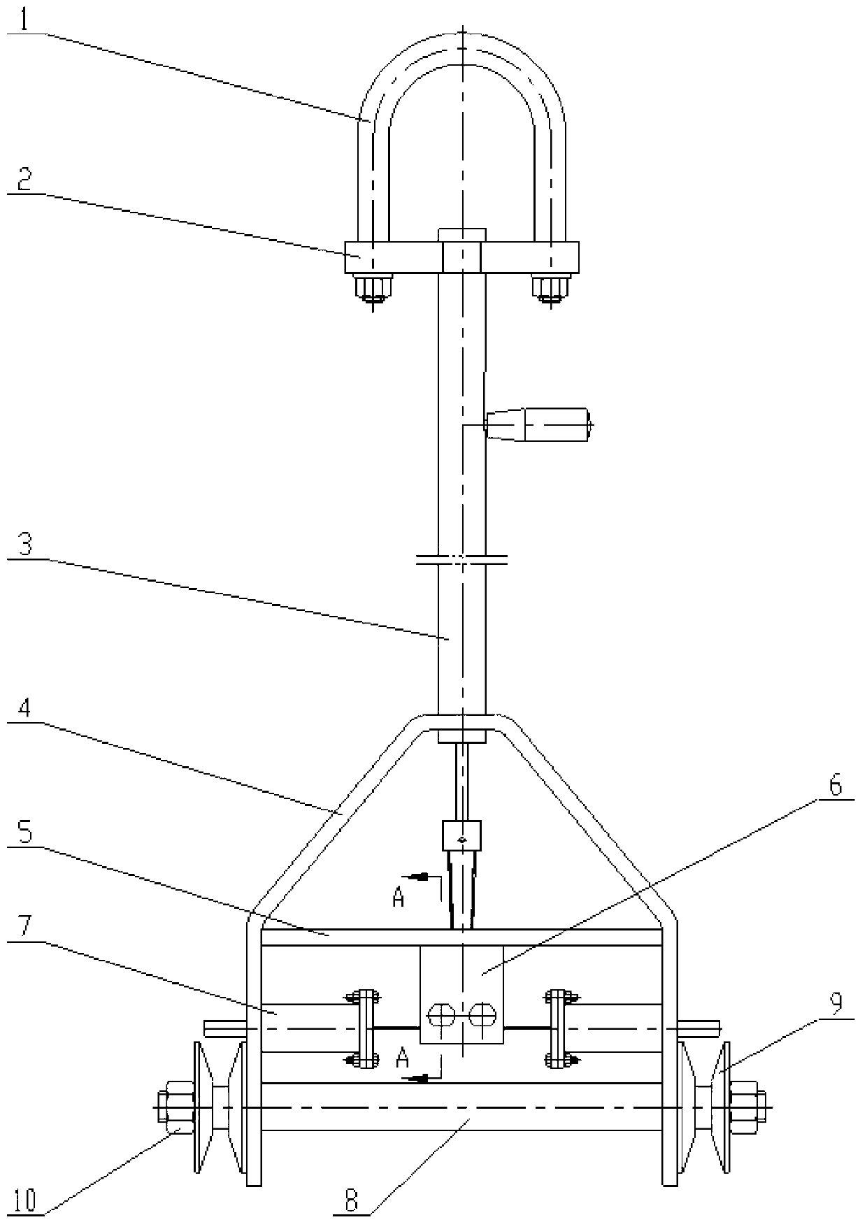
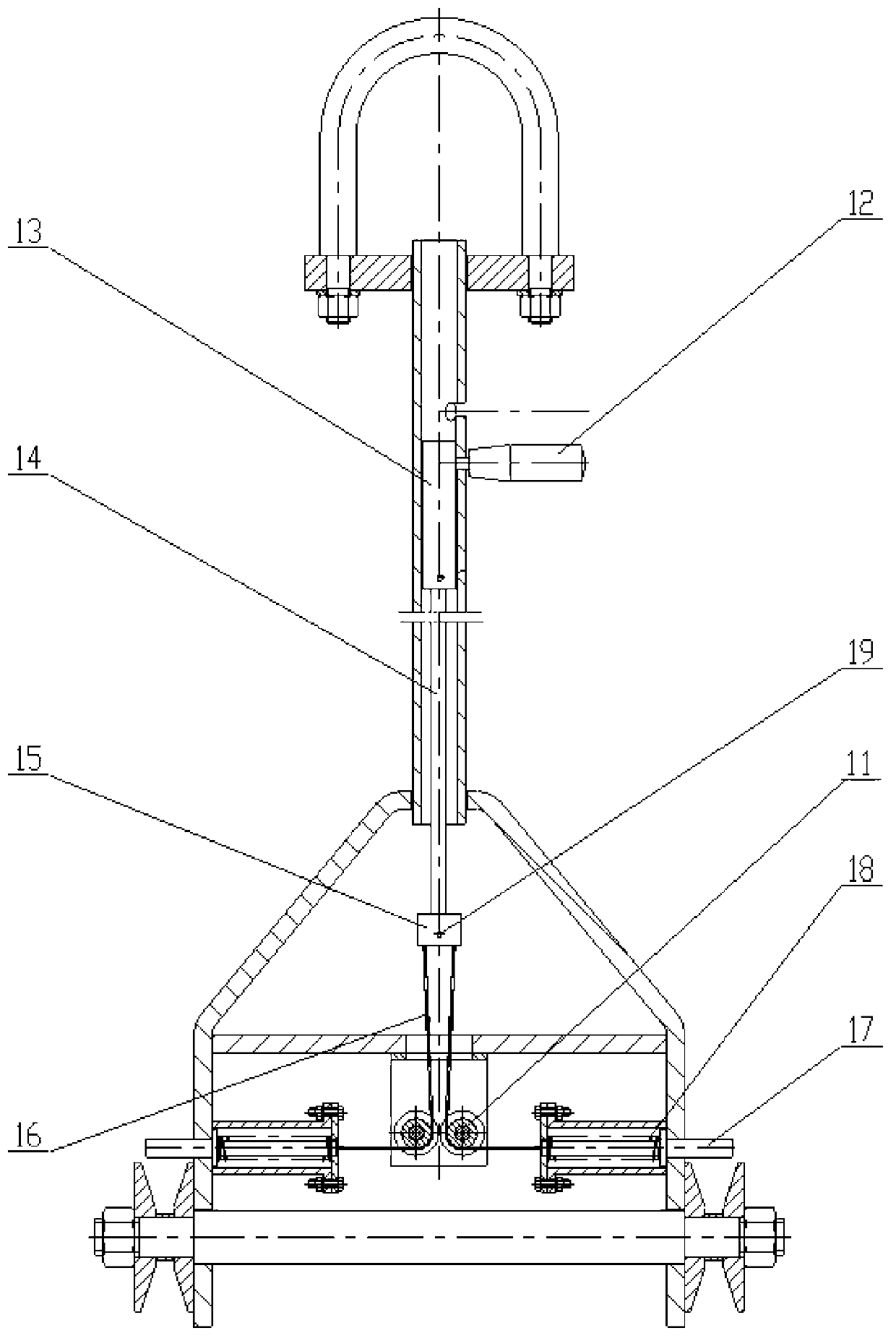
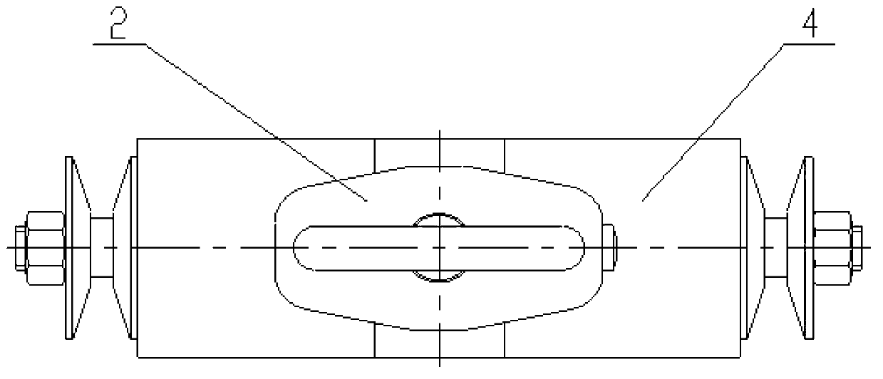
[0028] The long-rod spreader of the present invention is mainly composed of suspension rings, a suspension wheel device, a connecting pipe, and a latch mechanism. The suspension wheel device includes a suspension wheel frame and a suspension wheel whose axis is horizontally arranged on the suspension wheel frame. . Among them, the function of the lifting ring is to hook the hook of the lifting equipment (such as the crane in the factory building), and the function of the lifting wheel is to hook the hook-shaped lifting lug of the object to be hoisted; the connecting pipe is a long rigid pipe, specifically The length can be determined according to the actual application. The connecting pipe is set vertically, and its upper and lower ends are respectively connected with the suspension ring and the suspension wheel frame. The connecting pipe is provided with a handle that can slide vertically between the first and second working positions. The mechanism is arranged on the suspens...


PUM


Abstract

The invention discloses a long-pole spreader comprising a hanging ring (1), a hanging wheel rack (4), and hanging wheels (9). The hanging ring (1) and the hanging wheel rack (4) are rigidly connected through a connection pipe (3). A handle (12) which can slide between the first working position and a second working position is arranged on the connection pipe (3). A latch mechanism is arranged on the hanging wheel rack (4). The latch mechanism is connected with the handle (12) through a traction device. When the handle (12) is at the first working position, the latch mechanism extends out and shields wheel grooves of the hanging wheels (9). When the handle (12) is at the second working position, the latch mechanism retracts and leaves the wheel grooves of the hanging wheels (9). According to the long-pole spreader provided by the invention, the long rigid connection pipe is arranged between the hanging ring and the hanging wheel rank, and the latch mechanism is provided on the hanging wheel rank, such that the distance between operators and specific objects is ensured, and the operators are prevented from the harm of radioactivity or toxicity. Also, specific object lifting operation safety and reliability are ensured.

Description

technical field [0001] The invention relates to a sling, in particular to a long-rod sling, which is suitable for realizing remote operation and transshipment of heavy objects using hook-shaped lifting lugs. Background technique [0002] A spreader is a device for grabbing objects to be hoisted on a lifting device. At present, the most commonly used spreaders include hooks, rings, electromagnetic suckers and clamps. However, in some professional fields, it is also necessary to design corresponding special spreaders to meet their applications. For example, slab clamps, steel plate spreaders, and steel coil spreaders for steel mills; vacuum spreaders for precision electronics and pharmaceutical industries; container spreaders for port operations; container lifts for lifting fluid materials Barrels and hanging tanks, etc. [0003] Although the above-mentioned numerous forms of commonly used spreaders and special spreaders have been able to meet most of the application occasio...

Claims


Application Information

Patent Timeline
Patent Type & Authority Applications(China)
IPC IPC(8): B66C1/10
Inventor 王广开陈丽惠吴德慧降宇波彭思
Owner CHINA NUCLEAR POWER ENG CO LTD
Why Eureka
Try Eureka