
Servo device of trenching machine pipe coiling system

A technology of a follow-up device and a pipe system, which is applied in the direction of earth mover/shovel, construction, etc., can solve the problem that the spring drive device cannot meet the construction requirements of deep groove operations, the follow-up performance of the reducer drive device is not ideal, and the volume is large. and other problems, to meet the construction requirements of deep groove operations, the effect of constant tension control is good, and the volume is small.

Active Publication Date: 2014-11-26
中铁二十局集团西安工程机械有限公司
View PDF10 Cites 0 Cited by
  • Summary
  • Abstract
  • Description
  • Claims
  • Application Information

AI Technical Summary

Problems solved by technology

The existing grooving machine hydraulic hose reel drive technology includes reducer drive and spring drive, the follow-up of the reducer drive device is not ideal; the spring drive device cannot meet the construction requirements of deep groove operations, and the volume is relatively large

Method used

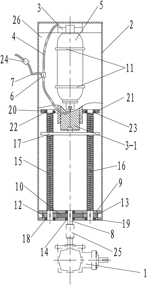
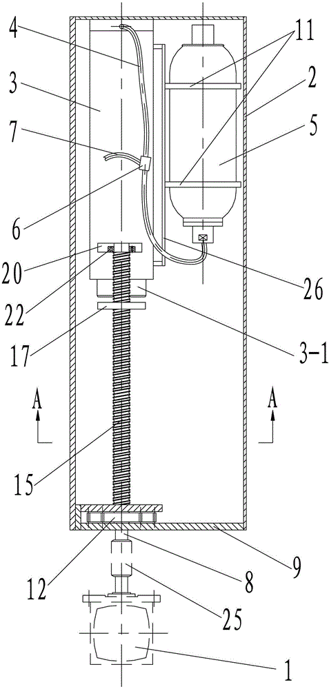
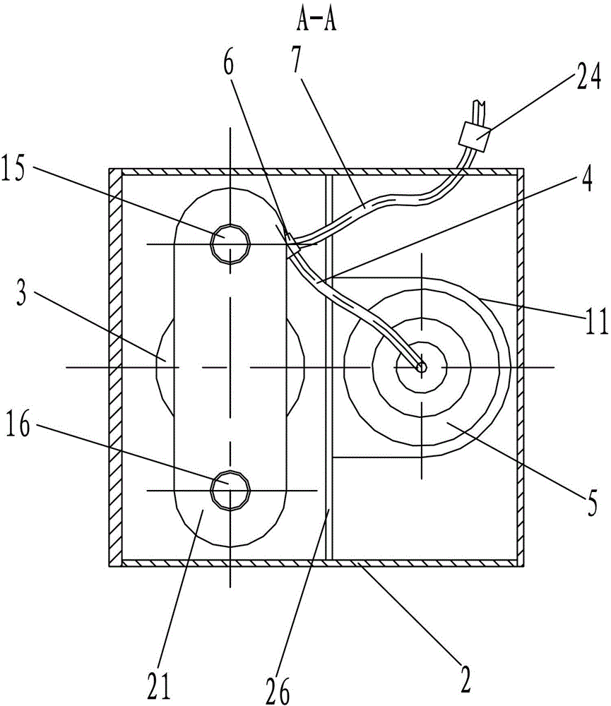

Image

  • Servo device of trenching machine pipe coiling system
  • Servo device of trenching machine pipe coiling system
  • Servo device of trenching machine pipe coiling system

Examples


Embodiment 1

[0044] like figure 1 , figure 2 and image 3As shown, the present invention includes a reducer 1 fixedly connected to the hydraulic hose reel 31 in the groove forming machine and a constant tension control mechanism for providing constant tension for the hydraulic hose 30 in the groove forming machine, and for outputting the reducer 1 The power is transmitted to the constant tension control mechanism to realize the transmission mechanism of the hydraulic rubber hose 30 and the steel wire rope 28 in the slotting machine; The accumulator 5 connected to the oil cylinder 3, the first oil pipe 4 is connected with the second oil pipe 7 connected with the hydraulic oil tank in the groove forming machine through the tee joint 6; the transmission mechanism includes the output of the reducer 1 The transmission shaft 8 connected to the shaft, the gear transmission mechanism connected to the transmission shaft 8, and the gear transmission mechanism connected to the gear transmission me...

Embodiment 2

[0056] combine Figure 5 The difference between this embodiment and Embodiment 1 is that the oil pressure controller includes a pressure sensor 24-3 and a solenoid valve 24-4 connected to the second oil pipe 7, and is used to control the pressure sensor 24-3 The detected signal is analyzed and processed and used for the controller module 24-5 that controls the solenoid valve 24-4 and the human-computer interaction device 24-6 connected with the controller module 24-5. The pressure sensor 24-3 It is connected with the input end of the controller module 24-5, and the solenoid valve 24-4 is connected with the output end of the controller module 24-5. All the other structures are the same as in Example 1.

[0057] During specific implementation, the controller module 24-5 may use a PLC module or a single-chip microcomputer, and the human-computer interaction device 24-6 may use a touch-type liquid crystal display.

[0058] When the present invention is used, it is different from...


PUM


Abstract

The invention discloses a servo device of a trenching machine pipe coiling system. The device comprises a speed reducer, a constant tension control mechanism and a driving mechanism, wherein the constant tension control mechanism is used for providing constant tension to a hydraulic rubber pipe in a trenching machine; the driving mechanism is used for transmitting the power output by the speed reducer to the constant tension control mechanism; the constant tension control mechanism comprises a plunger type hydraulic oil tank and an energy accumulator connected with the plunger type hydraulic oil tank through a first oil pipe; a second oil pipe is connected with the first oil pipe through a tee joint; the driving mechanism comprises a driving shaft, a gear driving mechanism and a screw rod driving mechanism; the driving shaft is connected with the speed reducer; the gear driving mechanism is connected with the driving shaft; and the screw rod driving mechanism is connected with the gear driving mechanism, used for converting the rotary movement of the gear driving mechanism into the linear movement of a plunger rod in the plunger type hydraulic oil tank and is connected with the plunger rod in the plunger type hydraulic oil tank. The servo device is compact in structure, reasonable in design, convenient to mount and use, complete in function, good in servo performance, good in constant tension control effect, stable and reliable in performance and high in popularization and application value.

Description

technical field [0001] The invention relates to the technical field of heavy industry machinery, in particular to a follower device for a pipe coiling system of a grooving machine. Background technique [0002] Grab bucket groove forming machine for underground diaphragm wall is one of the important construction machinery for underground diaphragm wall construction. When the slotting machine is working, the hydraulic hose must follow the main winch, that is, the length of the hydraulic hose winding / lowering reel is consistent with the length of the main winch lifting / lowering wire rope. The existing grooving machine hydraulic hose reel drive technology includes reducer drive and spring drive, and the followability of the reducer drive device is not ideal; the spring drive device cannot meet the construction requirements of deep groove operations, and its volume is relatively large. Contents of the invention [0003] The technical problem to be solved by the present invent...

Claims


Application Information

Patent Timeline
Patent Type & Authority Patents(China)
IPC IPC(8): E02F5/14E02F9/22
Inventor 侯润锋崔润兵李光明
Owner 中铁二十局集团西安工程机械有限公司
Learn More