Vacuum stop valve and hydraulic drive device and vacuumizing device formed by vacuum stop valve and hydraulic drive device

A technology for vacuuming devices and driving devices, which is applied in the direction of valve devices, valve operation/release devices, valve lifts, etc., and can solve problems such as insufficient flow inertia impact force, heavy maintenance workload, and blockage of vacuum cut-off valve channels. , to achieve the effect of not easy to wear, simple structure and fast closing

Inactive Publication Date: 2015-05-20
HUAZHONG UNIV OF SCI & TECH
View PDF6 Cites 0 Cited by
  • Summary
  • Abstract
  • Description
  • Claims
  • Application Information

AI Technical Summary

Problems solved by technology

This passive mechanical vacuum shut-off valve has the following disadvantages in use: 1) the workload of maintenance is very large
2) Strict working procedures must be implemented, especially in the hot mold and debugging stages, because the flow inertia impact force of the molten metal is insufficient at this time, and it is difficult to close the stop valve spool in time, which may cause blockage of the vacuum stop valve channel, not only Increase the cost of later maintenance, and seriously affect the work efficiency
3) The spool has high processing precision, is not wear-resistant, is prone to failure, and increases the cost of use

Method used


Image

  • Vacuum stop valve and hydraulic drive device and vacuumizing device formed by vacuum stop valve and hydraulic drive device
  • Vacuum stop valve and hydraulic drive device and vacuumizing device formed by vacuum stop valve and hydraulic drive device
  • Vacuum stop valve and hydraulic drive device and vacuumizing device formed by vacuum stop valve and hydraulic drive device

Examples


Embodiment Construction

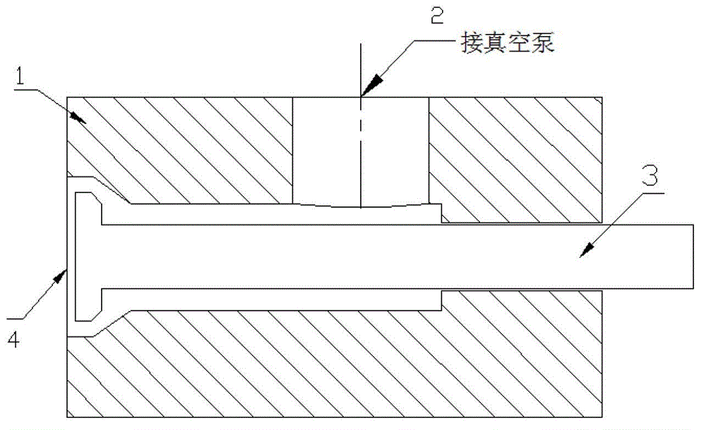
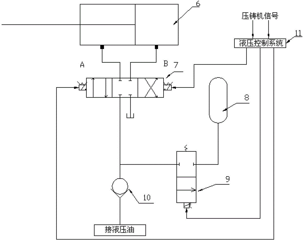
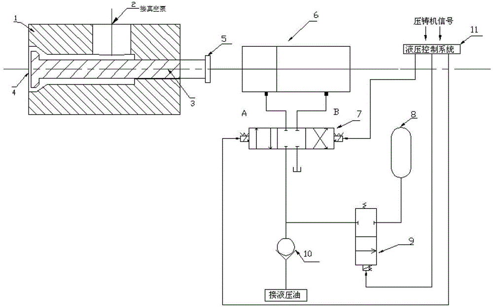
[0015] In order to solve the above-mentioned problems of the passive mechanical vacuum shut-off valve, the present invention proposes the single-piston hydraulically driven vacuum shut-off valve and its driving device. Its working principle is to use hydraulic drive mode to realize intelligent control of the vacuum shut-off valve according to the action signal of the die-casting machine, which can not only meet the high vacuum requirement of the mold cavity, but also effectively prevent the vacuum shut-off valve from being blocked, greatly reducing maintenance work Quantity and later maintenance costs, improve reliability and production efficiency.

[0016] The specific embodiments of the present invention will be further described below in conjunction with the accompanying drawings. It should be noted here that the descriptions of these embodiments are used to help understand the present invention, but are not intended to limit the present invention. In addition, the technic...


PUM


Abstract

The invention discloses a vacuum stop valve and a hydraulic drive device and a vacuumizing device formed by the vacuum stop valve and the hydraulic drive device. The stop valve comprises a valve body and a valve core. The hydraulic drive device comprises a hydraulic cylinder, a three-position four-way magnetic valve, an energy storage device, a two-position two-way magnetic valve, a one-way valve and a hydraulic control device. The vacuumizing device comprises the vacuum stop valve and the hydraulic drive device. A single valve core type is adopted in the vacuum stop valve, and therefore structure is simple, disassembly is convenient, abrasion can not happen easily, maintenance work amount in later stages is reduced greatly, and use cost is reduced. By adopting hydraulic drive, drive force is large, and motion reliability of the valve core is improved. By adopting a hydraulic high-speed drive circuit, the problem that hydraulic transmission is slow in response speed is solved, response speed of the vacuum stop valve is improved, quick closing is achieved, and blockage due to the fact that molten metal enters into the valve body is effectively prevented.

Description

technical field [0001] The invention belongs to the technical field of casting, and in particular relates to a vacuum cut-off valve, a hydraulic drive device and a vacuum pumping device formed thereof, which are used for high vacuum pressure casting. technical background [0002] In recent years, with the vigorous development of the automobile industry and the industry's urgent pursuit of automobile lightweight, replacing steel with aluminum has become the preferred method for most automobile manufacturers. Die casting has the advantages of high dimensional accuracy, low surface roughness, and high material utilization, and is more and more widely used in the field of automobile manufacturing. Due to die casting, the melt quickly fills the mold cavity under high pressure and high speed, so that the gas in the cavity cannot be discharged in time, so it stays in the casting and forms defects such as pores. Due to the existence of pores in castings, it is difficult to further ...

Claims


Application Information

Patent Timeline
Patent Type & Authority Patents(China)
IPC IPC(8): F16K1/00F16K31/122F16K51/02
Inventor 万里刘学强马超吴树森
Owner HUAZHONG UNIV OF SCI & TECH
Why Eureka
Try Eureka