

Refrigerating circuit for use in a motor vehicle
A technology for refrigeration circuits and motor vehicles, which is applied in the direction of refrigerators, refrigeration components, vehicle parts, etc., and can solve problems such as increased refrigerant mass flow
- Summary
- Abstract
- Description
- Claims
- Application Information
AI Technical Summary
Problems solved by technology
Method used
Image

Examples
Embodiment Construction
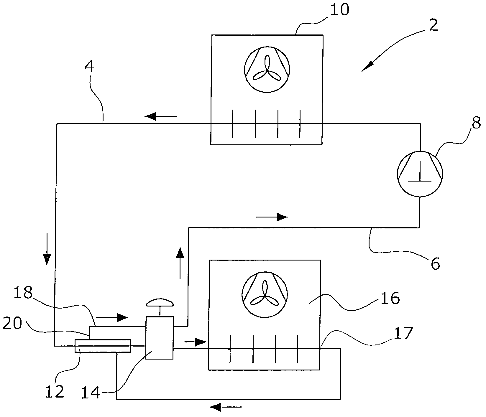
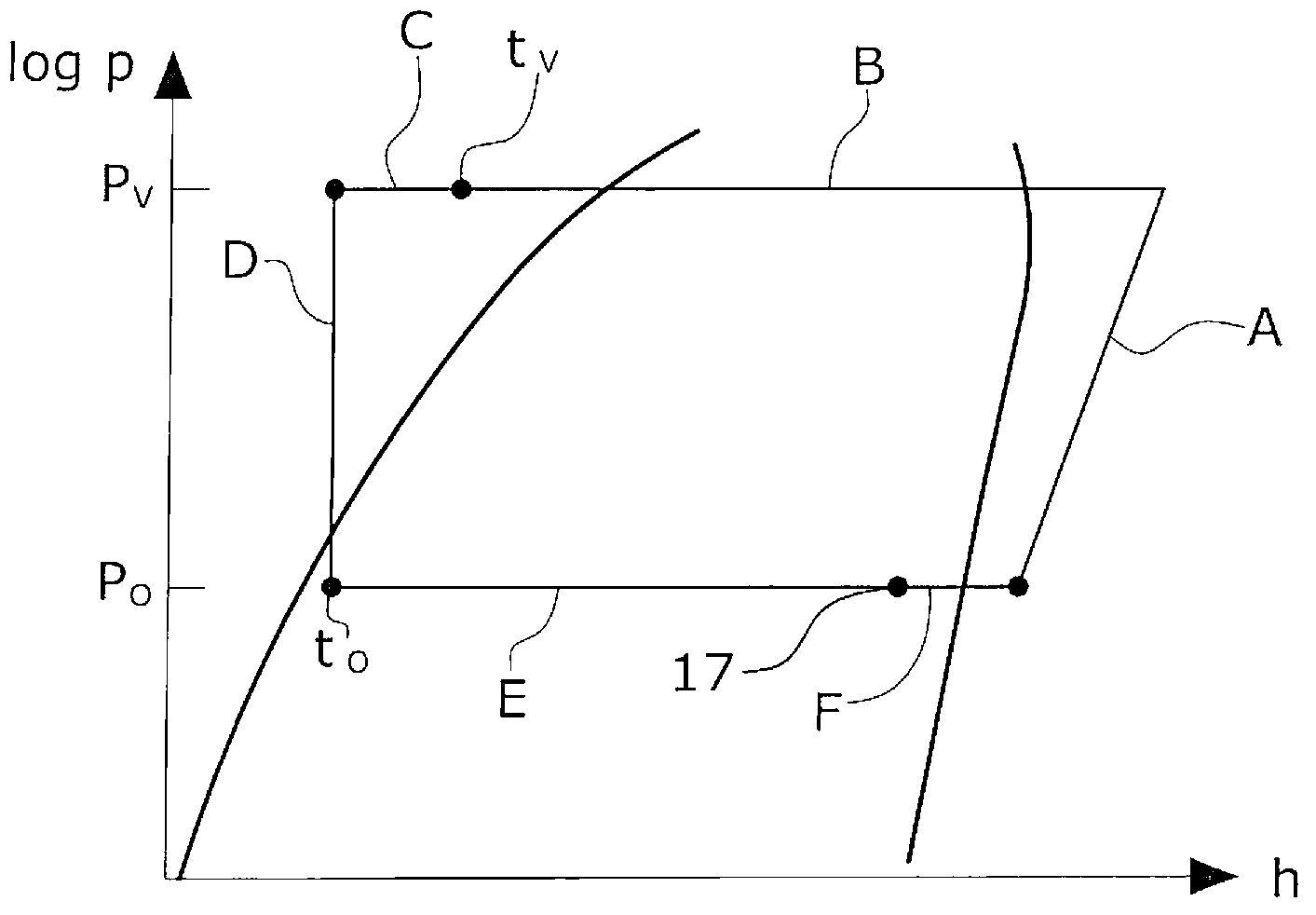
[0011] figure 1 A refrigeration circuit according to the invention is schematically shown and see now figure 2 The pressure-enthalpy diagram in is explained in more detail. The refrigeration circuit has a pressure line 4 and a suction line 6 . Pressure line 4 starts at the output of compressor 8 . Compressor 8 compresses the refrigerant to a liquefaction pressure P V , which in figure 2 is indicated by a state change A. Refrigerant at liquefaction pressure P V is transferred to the condenser 10, where the refrigerant releases heat, with the result that the refrigerant is in liquid state at the output of the condenser 10 and it has a liquefaction temperature t V . This state change in figure 2 Indicated by B.
[0012] From the condenser 10, the refrigerant is passed to the internal heat exchanger 12, in which the refrigerant in the pressure line 4 releases heat to the refrigerant in the suction line 6, which is shown by the pressure-enthalpy diagram The state chang...
PUM
 Abstract
Description
Claims
Application Information