Demodulating device and method for optical fiber Young interference optical path difference based on low coherent interference

A low-coherence interference and demodulation device technology, which is applied in the field of optical path difference demodulation method and device, can solve problems such as small measurement range, and achieve the effects of high working stability, high-precision demodulation, and convenient system adjustment

Active Publication Date: 2013-03-20
TIANJIN UNIV
View PDF4 Cites 15 Cited by
  • Summary
  • Abstract
  • Description
  • Claims
  • Application Information

AI Technical Summary

Problems solved by technology

However, the spatial optical path difference scanning range is li

Method used


Image

  • Demodulating device and method for optical fiber Young interference optical path difference based on low coherent interference
  • Demodulating device and method for optical fiber Young interference optical path difference based on low coherent interference
  • Demodulating device and method for optical fiber Young interference optical path difference based on low coherent interference

Examples


Embodiment 1

[0035] Embodiment 1: Optical path difference demodulation device based on low-coherence interference of optical fiber Young's interference

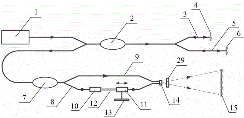
[0036] The system components include broadband light source, 3dB coupler, sensing interferometer, demodulation interferometer, correction interferometer and line array camera. Multimode optical fiber is used for optical signal transmission between the components.

[0037] Such as figure 1 As shown, the light emitted by the broadband light source 1 is divided into two paths of light through the 2×2 3dB coupler 2, and the two paths of light pass through the No. 1 arm 3 and the No. After the reflective end face 4 of the No. arm and the reflective end face 6 of the No. 2 arm are reflected back, a beam of light is synthesized through the 2×2 3dB coupler 2 again, and transmitted to the 2×1 3dB coupler 7; the 2×1 3dB coupler 7 again The light is divided into two paths, passing through the No. 1 arm 8 and the No. 2 arm 9 of the Mach-Zehnder inte...

Embodiment 2

[0045] Example 2: Fiber Young's interference optical path difference sensing method based on low coherence interference

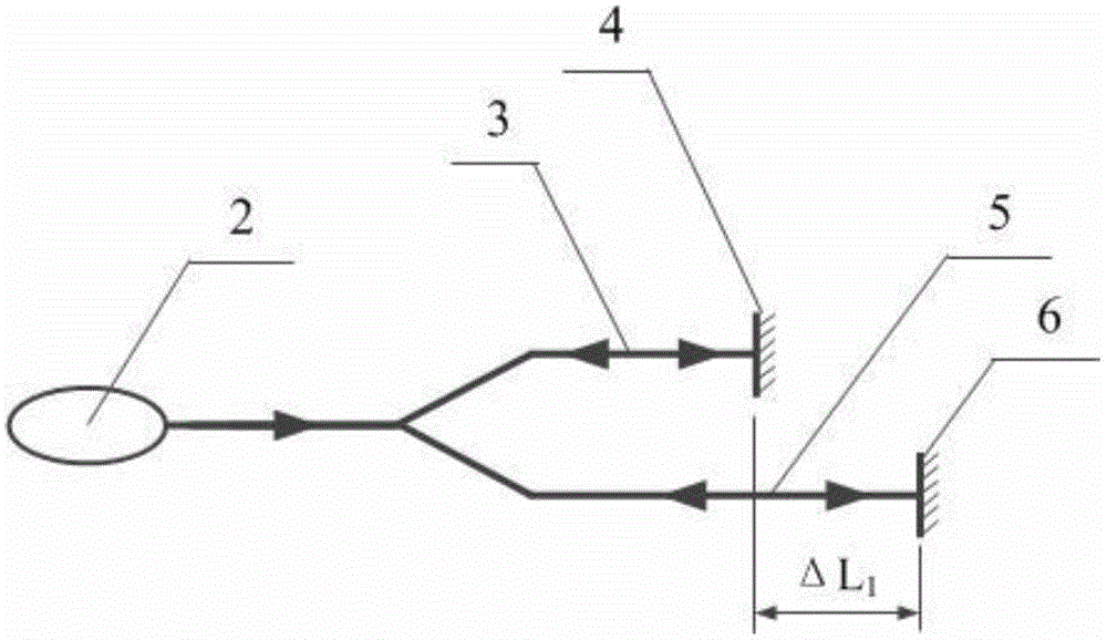
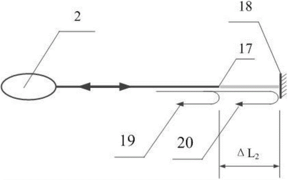
[0046] Optical path difference sensing method based on fiber optic Michelson interferometer such as figure 2 As shown, the 2×2 3dB coupler 2 divides the light into two paths, which are respectively input to the first arm 3 and the second arm 5 of the Michelson interferometer, and after being reflected on the end faces of the two arms, they are recombined into one beam of light. , due to the difference in the length of the two arms, the optical signal contains 2ΔL 1 The optical path difference information, changing the length of one of the arms, that is, changing the optical path difference sensing amount. In addition to the fiber-optic Michelson interferometer, the fiber-Perkin interferometer is also applicable, such as image 3 As shown: the light transmitted along the optical fiber is partially reflected at the end face 17 of the optical fiber to form ...

Embodiment 3

[0047] Embodiment 3: Fiber Young's interference optical path difference demodulation method based on low coherence interference

[0048] Such as Figure 4 As shown, the distance between the ends of the two optical fibers of the optical fiber Young's interferometer is d, the distance between the end face of the optical fiber and the line array camera is D, and the two beams of light are output to the light overlapping area 16 of the line array camera 15 to produce the final interference fringes, and are determined by the line Array camera 15 receives. Under the condition that d is much smaller than D, the optical path difference is linearly distributed in the light overlapping area 16, satisfying the formula: Δ=xd / D, where x represents the position. Then the normalized light intensity of the demodulated low-coherence interference fringes can be expressed as:

[0049] I ( λ , x ) =...


PUM


Abstract

The invention discloses a demodulating device for an optical fiber Young interference optical path difference based on low coherent interference. The demodulating device comprises a wideband light source, a 3dB coupler, a sensing interferometer, a demodulating interferometer, a calibration interferometer and a line array camera, wherein a multimode optical fiber is adopted in a light path formed by the components in sequence for optical signal transmission. A demodulating method mainly comprises the steps of optical path difference sensing, optical path difference demodulating and optical path difference calibration. Compared with the prior art, the demodulating device and the method integrate modes of space scanning and time scanning to conduct low coherent interference optical path difference demodulating; no mechanical movement is available; the stability is high; compared with the time scanning, the demodulating precision is not affected by moving precision of a scanning motor; the nano-level high precision demodulating can be realized; the optical path difference calibration of an overall system is realized by adjusting the optical path difference; in addition, a nano displacement platform is adopted to control the output optical path difference effectively; an optical path difference demodulating interval of the overall system is amended; and with the adoption of an optical fiber interferometer structural form, the system adjustment is facilitated and the working stability is high.

Description

technical field [0001] The invention relates to the field of optical fiber sensing, in particular to an optical path difference demodulation method and device. Background technique [0002] The principle of low-coherence interference technology for demodulation of optical path difference is that the optical path difference of the demodulation interferometer and the optical path difference of the sensing interferometer are used for scanning matching. Under the condition of strict matching of the optical path difference between the two, the output is the strongest Low-coherence interference signal, and finally realize high-precision demodulation of the optical path difference to be measured by accurately locating the envelope peak of the low-coherence interference signal. [0003] Low-coherence interferometry mainly includes time-scanning and space-scanning methods as optical path difference demodulation methods. The time-scanning type is that the optical path difference chan...

Claims


Application Information

Patent Timeline
IPC IPC(8): G01D5/26
Inventor 江俊峰刘铁根尹金德刘琨王双张以谟吴凡秦尊琪邹盛亮
Owner TIANJIN UNIV
Why Eureka
Try Eureka