
A cone-beam CT instantaneous scanning device and reconstruction method

A scanning device and cone beam technology, applied in the field of biomedical imaging and non-destructive testing, can solve the problems of long scanning time, low time resolution and high time resolution

Active Publication Date: 2020-11-06
CHONGQING UNIV
View PDF8 Cites 0 Cited by
  • Summary
  • Abstract
  • Description
  • Claims
  • Application Information

AI Technical Summary

Problems solved by technology

In 1983, R.A.Robb and E.A.Hoffman. proposed a fast-scanning device to scan organs such as the heart and lungs in the Proceedings of the Institute of Electrical and Electronics Engineers in 1983; the device installed multiple ray sources equidistantly in a semicircle On the surface, multiple detection devices installed on the opposite side of the ray source are used to record the projection data corresponding to each ray source, and the projection data of the scanned object at multiple angles can be obtained in a very short time. The time resolution is high, because all The ray sources are installed on the same circumference, and the scanning device has a complex structure and high cost
S.J.Schambach et al. proposed a multi-focus ray source and digital flat-panel detector for CT angiography of anesthetized mice in the Journal of the American Heart Association in 2009. During the acquisition of projection data, the mice within 40 seconds Continue to rotate 180 degrees at a constant speed to obtain 1200 pieces of projection data, and use the FBP (Filtered Backprojection) algorithm for image reconstruction. This method takes a long time to scan and has low time resolution.

Method used


Image

  • A cone-beam CT instantaneous scanning device and reconstruction method
  • A cone-beam CT instantaneous scanning device and reconstruction method
  • A cone-beam CT instantaneous scanning device and reconstruction method

Examples


Embodiment Construction

[0066] The preferred embodiments of the present invention will be described in detail below with reference to the accompanying drawings.

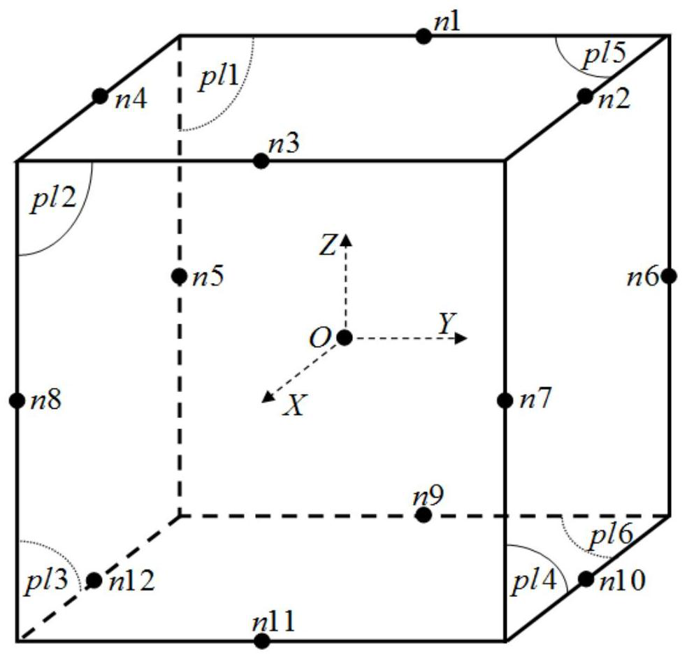
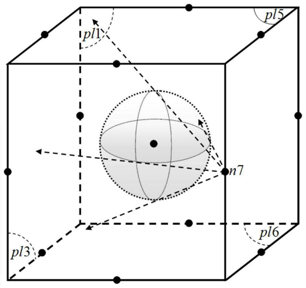
[0067] The working process of the cone beam CT instantaneous scanning device is as follows: figure 1 The shape of the cone-beam CT instantaneous scanning device is shown as a cube; the cone-beam CT instantaneous scanning device includes twelve X-ray sources based on carbon nanotubes, such as figure 2 The X-ray sources are respectively installed on the twelve sides of the cube, and multiple X-ray sources can be integrated X-ray focus, here is the simplest case as an example: each X-ray source has only one X-ray focus. All X-ray focal points are always aligned with the center O of the scanning device; the cone-beam CT instantaneous scanning device includes six high-speed flat-panel detectors, such as figure 2 pl1, pl2, pl3, pl4, pl5, pl6 respectively, six flat-panel detectors constitute the six surfaces of the cone-beam CT instantaneous s...


PUM


Abstract

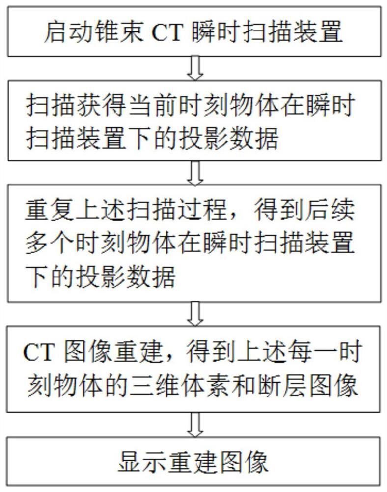
The invention relates to a cone beam CT instant scanning device and a reconstruction method. The reconstruction method includes steps of S1, placing an objective table in a scanning device, placing ascanned object on the objective table, and starting a scanning device; S2, starting all high-speed flat panel detectors, and scanning the object by an X-ray focal point in the scanning device, and immediately closing the X-ray focal point after collecting the projection data of the object; S3, traversing all X-ray focal points according to an appointed order and acquiring projection data of the object under the scanning device at the current moment; S4, repeating steps S2 and S3, acquiring the projection data of the scanned object under the scanning device at the next moment, and closing the cone beam CT instant scanning device; S5, rebuilding the object at every moment by a con beam CT reconstruction algorithm based on LO regularization, and acquiring a three-dimensional voxel and a faultage image of the scanned object at every moment and displaying them. The device can scan the object very quickly and is free from any mechanical movement during the scanning process; the time resolution is high.

Description

technical field [0001] The invention belongs to the technical field of biomedical imaging and nondestructive testing, and relates to a cone beam CT instantaneous scanning device and a reconstruction method. Background technique [0002] CT imaging technology has been successfully applied in the fields of biomedical imaging and non-destructive testing and has achieved great development. In order to meet the detection requirements of objects of different structures and sizes, different scanning methods and reconstruction algorithms have been developed. Most scanning methods scan static objects. During the scanning process, the object only moves in rotation or translation, and the size, shape and internal structure of the object will not change with time; the scanning method and reconstruction algorithm for static objects can obtain high spatial resolution. Reconstructed images at a high rate and meet the actual needs. [0003] In the field of industrial non-destructive testi...

Claims


Application Information

Patent Timeline
Patent Type & Authority Patents(China)
IPC IPC(8): A61B6/03G01N23/046
CPCA61B6/032A61B6/4085A61B6/4208A61B6/5205G01N23/046
Inventor 曾理龚长城王成祥
Owner CHONGQING UNIV
Learn More