
Frequency detection method used for microgrid system

A technology of frequency detection and micro-grid, applied in the direction of frequency measurement devices, etc., can solve the problems of large detection errors, errors, zero-crossing offset detection, etc., and achieve the effect of simple algorithm, cost saving, and less occupation

Active Publication Date: 2013-03-20
ZHEJIANG EIFESUN ENERGY TECH
View PDF4 Cites 14 Cited by
  • Summary
  • Abstract
  • Description
  • Claims
  • Application Information

AI Technical Summary

Problems solved by technology

However, because the hardware circuit is susceptible to interference, the zero-crossing point will be shifted to cause detection errors. When the voltage waveform is distorted due to voltage fluctuations, flicker, harmonics, etc., it will cause large detection errors.

Method used


Image

  • Frequency detection method used for microgrid system
  • Frequency detection method used for microgrid system
  • Frequency detection method used for microgrid system

Examples


Embodiment Construction

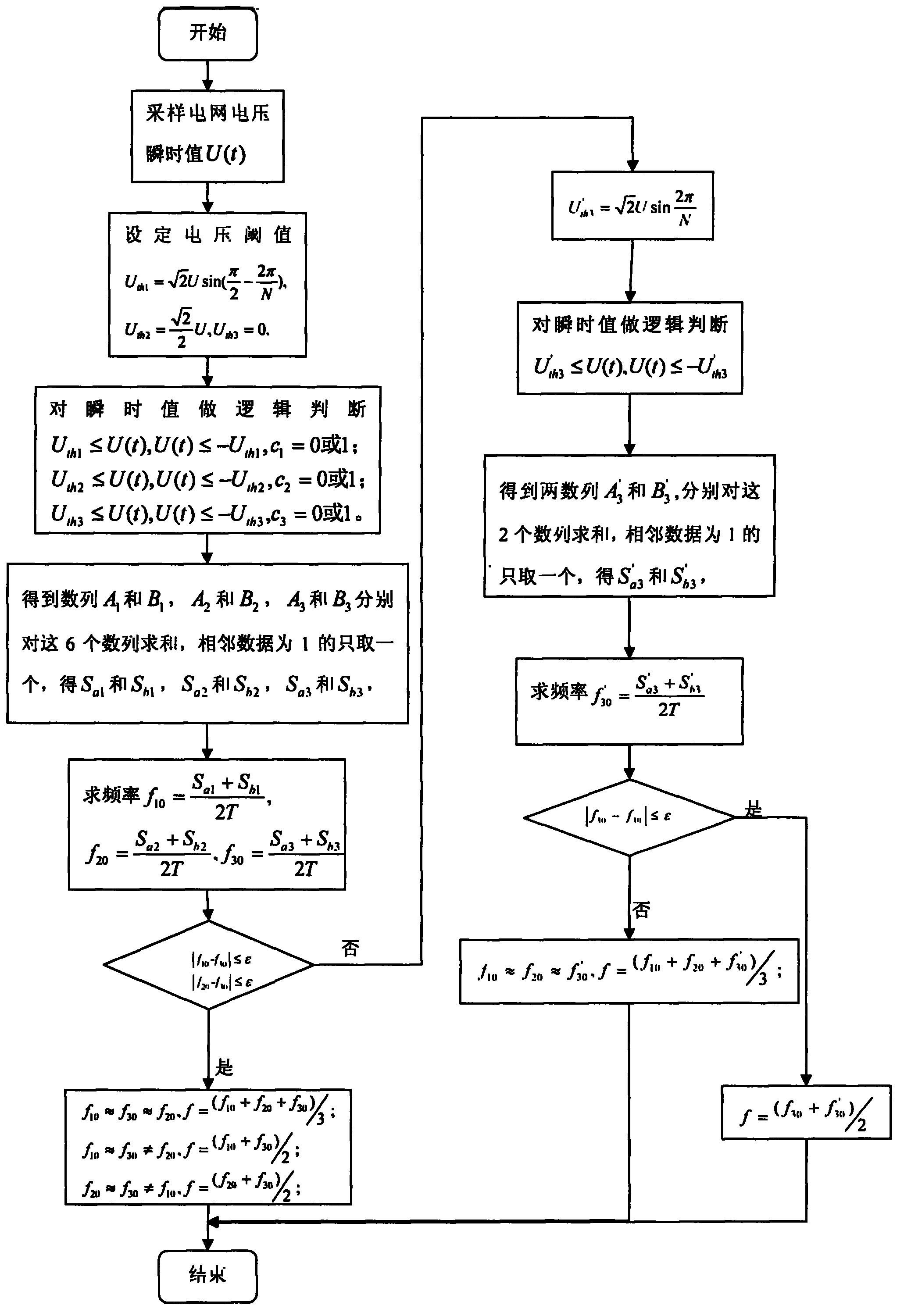
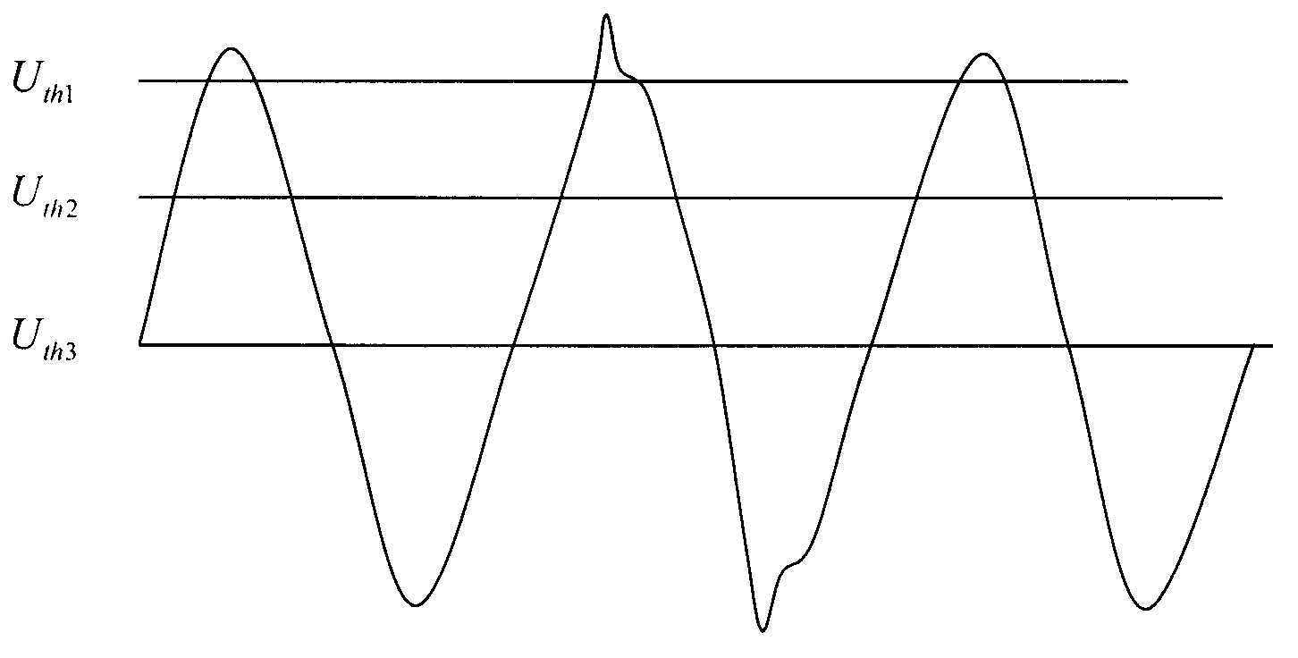
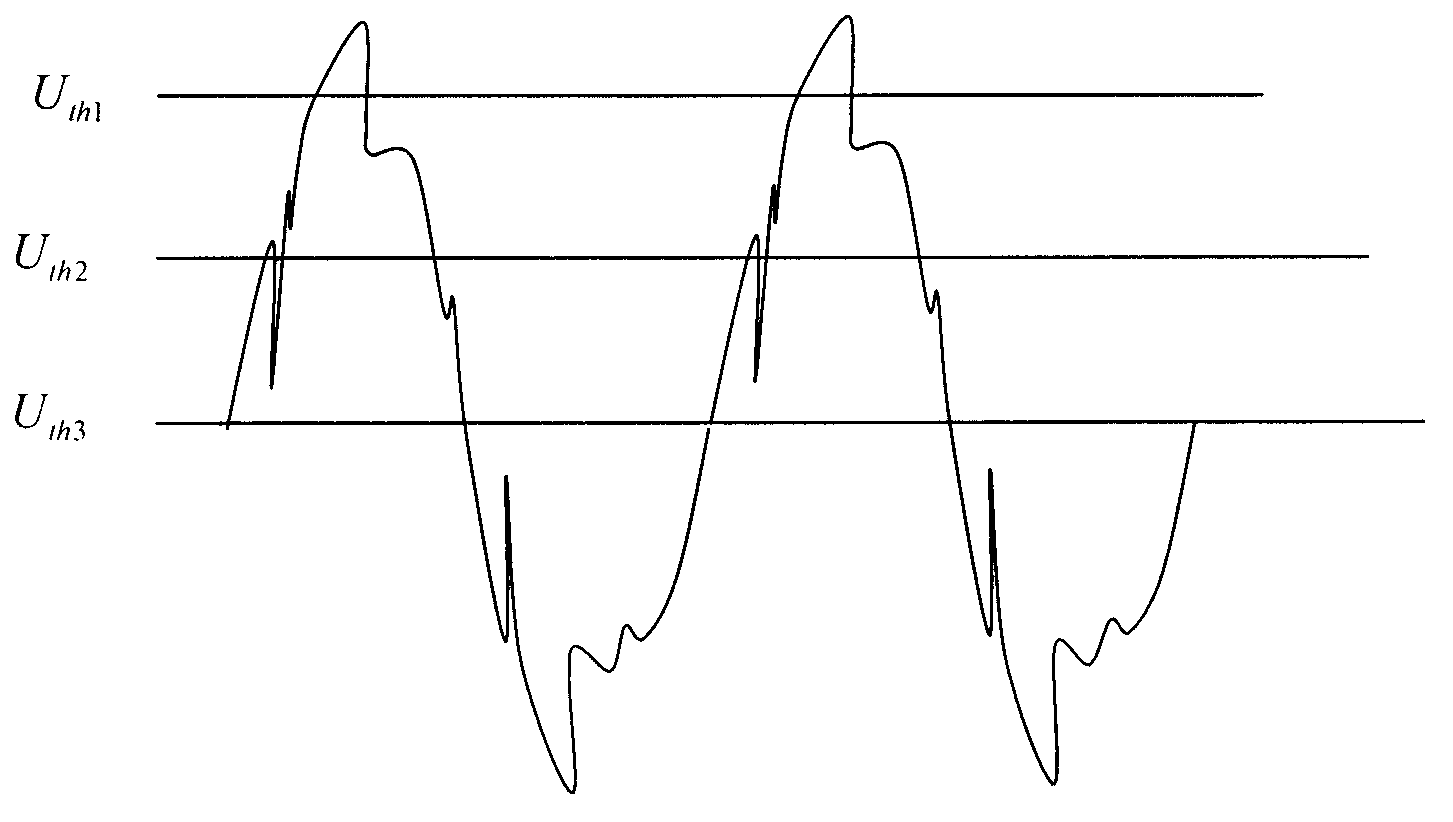
[0034] Combine below figure 1 , figure 2 , image 3 , Figure 4 , Figure 5 , Figure 6 , to describe the frequency detection method of the microgrid system in detail. It should be emphasized that the following descriptions are illustrative only and not intended to limit the scope and application of the present invention.

[0035] (1) The data acquisition device collects the instantaneous value U(t) of the grid voltage. The number of sampling times in one cycle of the grid voltage is N times, and the data sampling time length is T (generally 10 seconds). For the grid sampling frequency of 50Hz frequency is f 1 = 50 N ;

[0036] (2) Set 3 reference thresholds U th1 , U th2 , U th3 ,, if the rated voltage of the power grid is U(t), and the number of sampling points in one cycle is N, then there must be an instantaneous value of the sampling voltage greater than or equal to then take...


PUM


Abstract

The invention discloses a frequency detection method used for a microgrid system. The frequency detection method includes that firstly data sampling is carried out on microgrid voltage, the number of sampling in each cycle is N, and the time span of the sampling is T; secondly three voltage threshold values are set according to nominal voltage and sampling frequency; thirdly according to the voltage threshold values, the number of voltage cycles within sampling time is obtained in the method of logical judgment, and initial frequency under the three voltage threshold values is respectively obtained; and fourthly the initial frequency is analyzed and judged, frequency with large errors due to wave distortion is eliminated, and then a precise grid frequency value is obtained. The method is simple and convenient to carry out, easy to achieve, and high in precision.

Description

technical field [0001] The invention relates to a frequency detection method for a micro-grid system, and belongs to the technical field of power system power quality measurement. Background technique [0002] The development of society and the advancement of science and technology have increased people's demand for electricity, while the shortage of traditional energy sources and the urgent need for environmental protection have prompted the power industry to continue to develop new energy sources while expanding and improving the centralized power supply of the original large grid. The utilization rate of renewable energy has formed a new power supply mode combining large power grid and distributed power generation. [0003] Distributed power generation energy supply refers to the use of various available decentralized energy sources, including renewable energy (solar energy, wind energy, etc.) , the most efficient way to use. The adoption of distributed power generation...

Claims


Application Information

Patent Timeline
Patent Type & Authority Applications(China)
IPC IPC(8): G01R23/02
Inventor 刘士荣姜碧光张晓东李久广胡浙东
Owner ZHEJIANG EIFESUN ENERGY TECH
Learn More