Electric rotating locating device used for camera polarized lens

A polarized lens and positioning device technology, applied in the direction of using feedback control, etc., can solve problems such as difficulty in manual rotation

Active Publication Date: 2013-03-20
广州市信康科技电子有限公司
View PDF4 Cites 12 Cited by
  • Summary
  • Abstract
  • Description
  • Claims
  • Application Information

AI Technical Summary

Problems solved by technology

[0002] At present, surveillance cameras select and filter light from a certain direction by manually rotating the polarizing lens on the len

Method used


Image

  • Electric rotating locating device used for camera polarized lens
  • Electric rotating locating device used for camera polarized lens
  • Electric rotating locating device used for camera polarized lens

Examples


Embodiment Construction

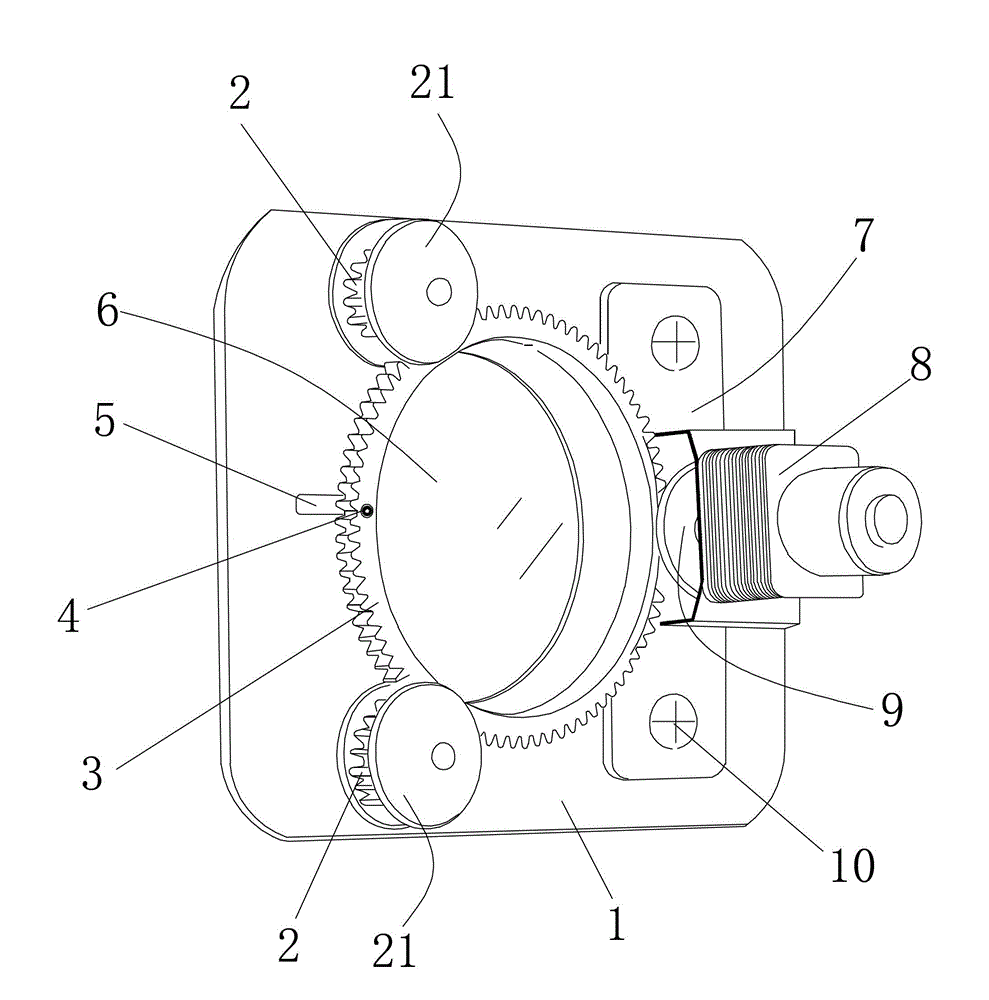
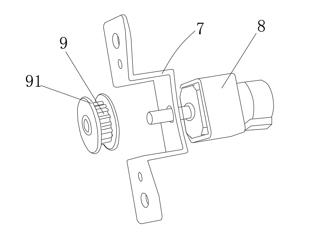
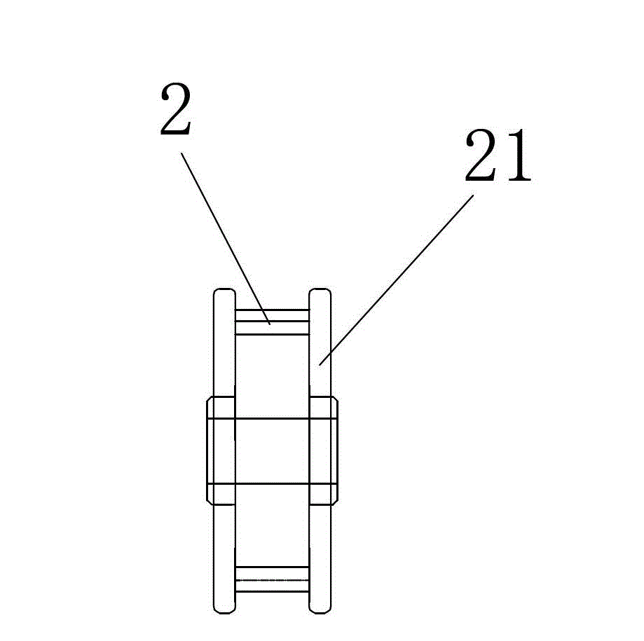
[0024] Such as Figure 1 to Figure 6 Shown is an electronically controlled rotary positioning device for polarized lenses of cameras, which includes a polarized lens 6, a polarized lens gear 3, a driving mechanism, a control mechanism for the polarized lens gear, a support mechanism for the polarized lens gear, and a base 1, The driving mechanism, the control mechanism of the polarizing lens gear and the supporting mechanism of the polarizing lens gear are all arranged on the base 1, the polarizing lens gear 3 is a hollow ring gear, the middle part of the polarizing lens gear 3 has a step, and the polarizing lens 6 is embedded in the On the steps of the polarizing lens gear 3, the driving mechanism contacts the polarizing lens gear 3, drives the polarizing lens gear 3 to rotate, the supporting mechanism of the polarizing lens gear meshes with the polarizing lens gear 3, suspends the polarizing lens gear 3, and the polarizing lens gear The control mechanism can detect and sense...


PUM


Abstract

The invention discloses an electric rotating locating device used for a camera polarized lens. The electric rotating locating device used for the camera polarized lens comprises a polarized lens, a polarized lens gear, a driving mechanism, a control mechanism of the polarized lens gear, a supporting mechanism of the polarized lens gear and a substrate. The driving mechanism, the control mechanism of the polarized lens gear, and the supporting mechanism of the polarized lens gear are arranged on the substrate. The polarized lens gear is a hollow ring gear. The polarized lens is embedded in the polarized lens gear which is driven by the driving mechanism to rotate. The supporting mechanism of the polarized lens is meshed with the polarized lens gear and used for supporting the polarized lens gear in a suspension mode. The control mechanism of the polarized lens gear is capable of detecting and sensing a rotating location and a rotating angle of the polarized lens gear, issuing pulse command to the driving mechanism, and controlling movement of the driving mechanism. Therefore, the polarized lens gear is driven to rotate to a set rotation angle. The electric rotating locating device used for the camera polarized lens is capable of controlling rotation remotely and locating accurately the polarized lens.

Description

technical field [0001] The invention relates to a camera component, in particular to an electronically controlled rotary positioning device for a camera polarized lens. Background technique [0002] At present, surveillance cameras select and filter light from a certain direction by manually rotating the polarizing lens on the lens. When the surveillance camera is installed in a waterproof box or installed in a high place or far away, manual rotation becomes difficult. . At the same time, we also have problems describing the rotation angle of the polarizer. For example, we often say that if you rotate it 30 degrees to the right, the result will be: 30 degrees vertically to the right, 30 degrees upward horizontally, and 30 degrees downward horizontally, etc. Multiple understandings. How to control the rotation of the polarized lens and precisely position the polarized lens has become a difficult technical problem in camera components. Contents of the invention [0003] T...

Claims


Application Information

Patent Timeline
IPC IPC(8): G05D3/12
Inventor 黄锐敏
Owner 广州市信康科技电子有限公司
Why Eureka
Try Eureka