
Cooling ring for fluorescent tube

A technology of fluorescent lamps and heat dissipation rings, which is applied to the parts and components of gas discharge lamps, can solve the problems of inability to truly realize industrialization, and achieve the effects of simple structure, prolonged service life, and convenient production and assembly.

Inactive Publication Date: 2013-03-20
宫锡和
View PDF4 Cites 0 Cited by
  • Summary
  • Abstract
  • Description
  • Claims
  • Application Information

AI Technical Summary

Problems solved by technology

Although it has the effect of heat dissipation and cooling, it also has the effect of shielding the instantaneous high temperature and electric spark between the electrodes when the lamp is started, but according to this technical requirement, it has been proved by many tests that it cannot really realize industrialization. It is just a technical conception. That's all

Method used


Image

  • Cooling ring for fluorescent tube
  • Cooling ring for fluorescent tube
  • Cooling ring for fluorescent tube

Examples


Embodiment Construction

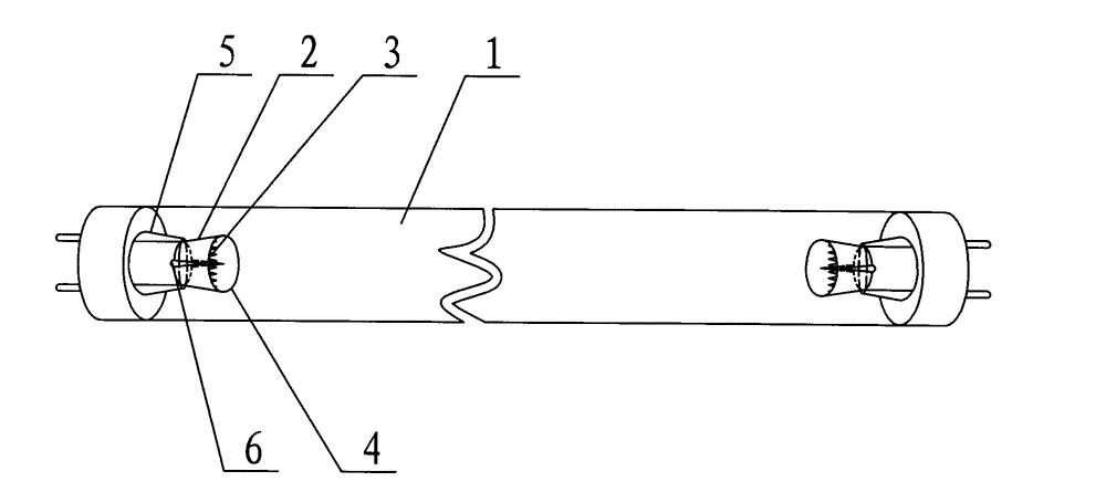
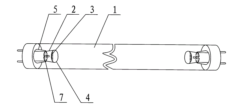
[0015] From Figure 1-2 It can be seen from the figure that the cooling ring for fluorescent tubes includes a glass tube 1 whose inner wall is coated with phosphor powder. kind of shape. The two ends of the glass tube 1 are respectively sealed and installed with a glass stem 5 and a filament 3, and two electrodes 2 connected to the filament 3 are installed on the glass stem 5, and each of the electrodes 2 is equipped with a large conical tube facing the center of the glass tube. Non-metallic ring4.

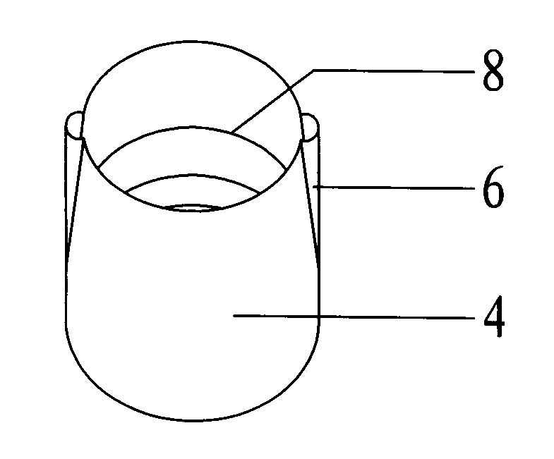
[0016] Embodiment 1 from figure 1 It can be seen from the figure that the conical non-metallic ring 4 is vertically provided with two raised grooves 6 from the inside to the outside. When installing, align the two grooves 6 protruding from the inside to the outside with the two electrodes 2, and then rotate it to closely connect with the two electrodes 2.

[0017] Embodiment 2 from figure 2 It can be seen from the figure that the conical non-metallic ring 4 is vertically pro...


PUM


Abstract

The invention relates to a cooling ring for a fluorescent tube. The cooling ring comprises a glass tube with fluorescent powder on the inner wall, glass stems and filaments are installed at two ends of the glass tube in a sealing mode respectively, two electrodes connected with the filaments are arranged and supported on the glass stems, tapered nonmetallic rings are sleeved on the outer portions of the filaments and the electrodes in the glass tube respectively, and the tapered nonmetallic rings are tightly connected with the two electrodes. The tapered nonmetallic rings both can shield the high temperature and electric sparks produced instantaneously between the electrodes during the starting of the fluorescent tube and play a role in cooling the electrodes and the filaments rapidly, and reduce the filament burn-out rate. The cooling ring for the fluorescent tube is simple and reasonable in structure, and prolongs the fluorescent tube service life greatly.

Description

technical field [0001] The invention relates to a lighting appliance, in particular to a cooling and cooling ring for a fluorescent lamp tube. Background technique [0002] At present, it is known that incandescent lamps will gradually withdraw from the lighting market in 2012, and will be replaced by energy-saving fluorescent lamps and LED lamps. Although fluorescent lamps save energy significantly, they are summarized as energy-saving but not money-saving products due to their limited lifespan. The reason for the short life of the fluorescent lamp is that the filament is blown out by the high temperature instantaneously generated between the electrode and the electrode when the lamp is started. However, due to the high cost and high price of LED lights, they cannot be accepted by most of the public. Chinese patent 201120506146.5 Cooling and heat dissipation ring for fluorescent lamp tube. The two electrodes in the glass tube are each covered with a horn-shaped metal cove...

Claims


Application Information

Patent Timeline
Patent Type & Authority Applications(China)
IPC IPC(8): H01J61/52
Inventor 孙国巨乔永平宫锡和宫飞雪
Owner 宫锡和
Learn More