
Atomization device and ultrasonic humidifier

A technology of atomization device and transducer, which is applied to spray device, liquid spray device, air humidification system, etc., can solve the problems of complicated operation, high processing and manufacturing cost, complicated manufacturing process, etc., so as to reduce the manufacturing cost and simplify the structure. , the effect of reducing the difficulty of the manufacturing process

Active Publication Date: 2013-03-27
佛山市汉立电子科技有限公司
View PDF7 Cites 18 Cited by
  • Summary
  • Abstract
  • Description
  • Claims
  • Application Information

AI Technical Summary

Problems solved by technology

Therefore, the existing ultrasonic humidifier has the following defects: since the bottom structure of the water tank assembly needs to be used to control the flow of water from the bottom of the water tank into the machine base, the structure of the water tank assembly is complex and requires high sealing, resulting in complex manufacturing processes, High processing and manufacturing costs, poor reliability and low atomization efficiency
If the amount of water flowing from the water tank assembly to the transducer is too much, even when the water level is below the top of the energy gathering cover, the improvement effect of the energy gathering cover on increasing the amount of atomization is not obvious. Therefore, the existing energy gathering cover is not only suitable for The performance is poor, and the atomization enhancement effect is not ideal
[0007] 3. Since the energy-gathering cover is fixed on the shell of the atomizer, not only is it inconvenient to install, but also the energy-gathering cover needs to be disassembled from the shell when cleaning, which is cumbersome to operate and inconvenient to clean.

Method used


Image

  • Atomization device and ultrasonic humidifier
  • Atomization device and ultrasonic humidifier
  • Atomization device and ultrasonic humidifier

Examples


Embodiment Construction

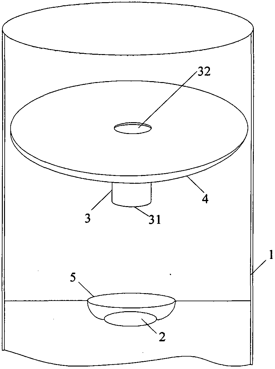
[0029] The present invention proposes an atomization device and an ultrasonic humidifier, in which an atomization enhancement part is set floating in the liquid above the transducer, so that the liquid above the transducer can produce a better atomization effect when it is at any liquid level . Since the present invention can work normally when the liquid on the transducer is at any liquid level that changes dynamically, it is no longer necessary to use the bottom structure of the water tank assembly to control the liquid level on the transducer to keep fixed, so that it can get rid of the ultrasonic wave The humidifier relies on the water tank components to achieve the purpose of simplifying the structure and improving the atomization effect.

[0030] like figure 1 As shown, the atomization device proposed by the present invention includes: a water tank 1 for containing atomized liquid (such as water, medicament, fragrance, etc.), the bottom of the water tank 1 is fixed with...


PUM


Abstract

The invention discloses an atomization device and an ultrasonic humidifier, wherein the atomization device comprises a transducer, an atomization enhancing part and a buoyancy part, wherein the atomization enhancing part is arranged in liquid above the transducer in a floating manner and comprises a guide cylinder with a through hole, an axial center line of the through hole is consistent to an axial center line of the transducer, and the buoyancy part is connected with the guide cylinder and can floats on the surface of the liquid above the transducer. According to the invention, the existing ultrasonic humidifier is revolutionarily improved, when the liquid above the transducer is at any liquid level height, the atomization device and the ultrasonic humidifier provided by the invention can generate good atomization effect, thereby being adapted to a use environment with any liquid level height, greatly increasing the atomization efficiency, and having the advantages of high adaptability, simple structure, low material consumption, low manufacture cost, convenience in installation, easiness in cleaning and the like.

Description

technical field [0001] The invention relates to an atomizing device, in particular to an atomizing device and an ultrasonic humidifier for liquid atomization. Background technique [0002] One of the existing liquid atomization methods is to adopt an ultrasonic atomization scheme, and the liquid (such as water, medicine, fragrance) is atomized by an ultrasonic atomizer. Ultrasonic humidifier is one of the applications using ultrasonic atomization scheme. [0003] A traditional ultrasonic humidifier includes a machine base and a water tank assembly. The water tank assembly is connected above the machine base. An atomizing device is installed on the machine base. The atomizing device has a transducer (also called an atomizing sheet or a piezoelectric ceramic sheet ). When enough water is added to the water tank assembly, the bottom structure (water valve) of the water tank assembly is used to control the water from the bottom of the water tank to flow into the machine base a...

Claims


Application Information

Patent Timeline
Patent Type & Authority Applications(China)
IPC IPC(8): B05B17/06F24F6/12
Inventor 杨义根
Owner 佛山市汉立电子科技有限公司
Learn More