Marching type automatic gripping feeding device

An automatic feeding, step-by-step technology, applied in the directions of feeding devices, positioning devices, storage devices, etc., can solve the problems of large device occupancy, maintaining the horizontal posture of the clamping end, deformation and damage of the outlet plate edge, etc. Occupied space, reduced necessary height, increased degree of freedom effect

Inactive Publication Date: 2013-03-27
BEIJING STAR RIVER INTEGRATED EQUIP TECH
View PDF8 Cites 3 Cited by
  • Summary
  • Abstract
  • Description
  • Claims
  • Application Information

AI Technical Summary

Problems solved by technology

[0002] Automatic pulling and feeding is an important process link in the plate stamping production line. At present, the automatic clamp feeding device on the plate stamping production line is driven by three cylinders. During the stamping process, the plate moves downward under the action of the stamping force and is horizontal Pull back a certain distance in the direction, because the rotation freedom of the clamping end of the existing automatic feeding device is too small, it is impossible to maintain the horizontal posture of the clamping end within the follow-up range, which will cause deformation and damage to the edge of the outlet plate to varying degrees, affecting The quality of the export plate and the large space occupied by the device will affect the speed of the plate pulling and cause unnecessary cost waste

Method used


Image

  • Marching type automatic gripping feeding device
  • Marching type automatic gripping feeding device
  • Marching type automatic gripping feeding device

Examples


Embodiment Construction

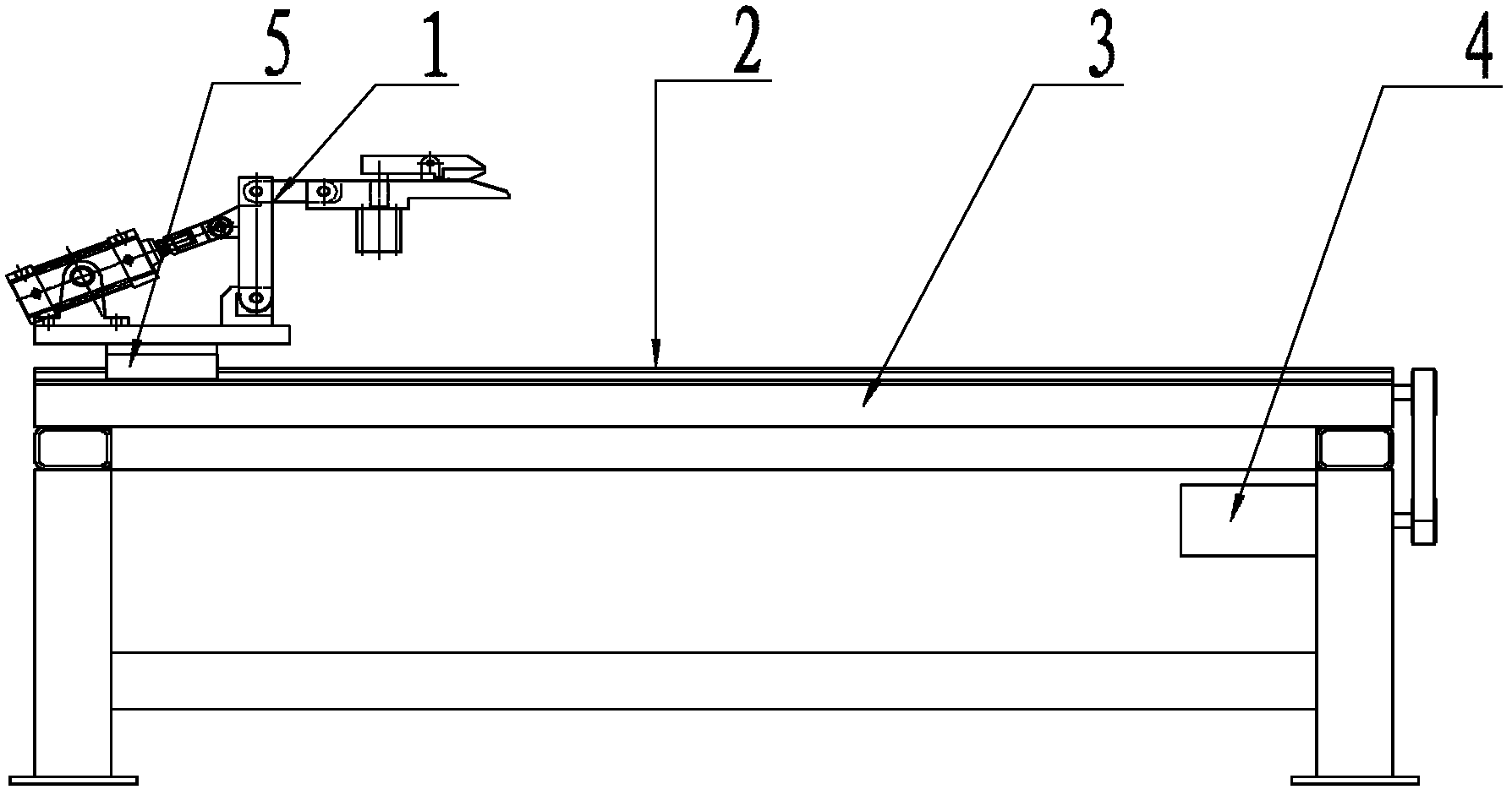
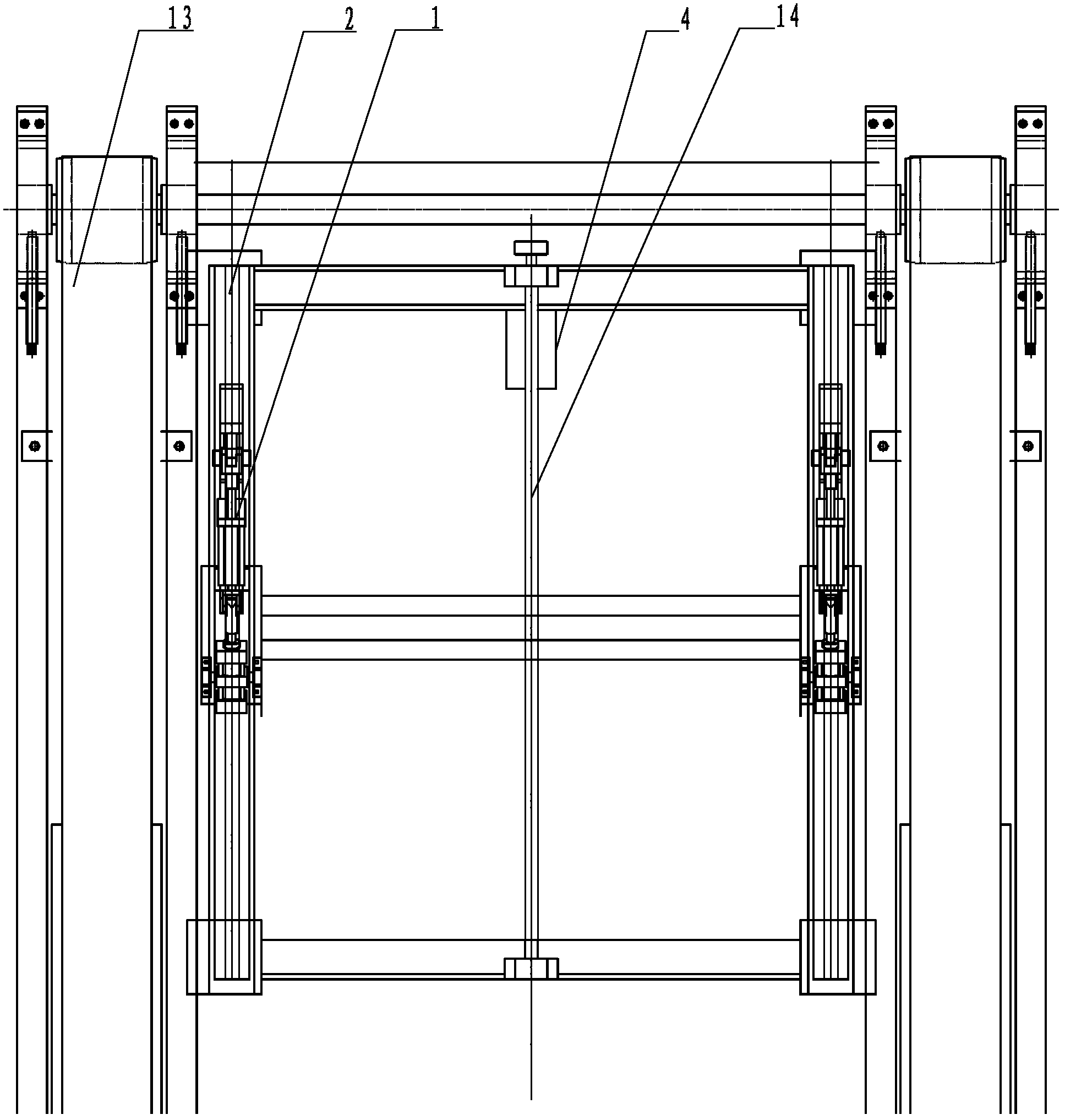
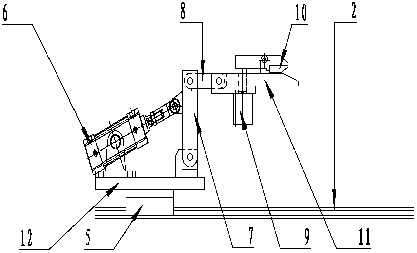
[0011] Pneumatic clamps 1 are fixedly installed on sliders 5 respectively through bases 12, and sliders 5 slide synchronously on two parallel sliding guide rails 2 respectively. The sliding guide rails 2 are supported by brackets 3, and a liftable belt conveyor 13 is installed on the outside of them. , The ball screw 14 is installed in the middle of the two sliding guide rails 2 and is parallel to the guide rails. The ball screw 14 is driven by the servo motor 4 and drives the slider 5 on the sliding guide rail 2 . Pneumatic clamp 1 comprises cylinder 6, connecting rod 7, hinge 8, thin cylinder 9, upper clamping plate 10 and lower clamping plate 11, and the center of gravity of upper clamping plate (10) is at the tail end of a certain distance from pin shaft, and cylinder 6 and connecting rod 7 The bottom ends of the cylinders are respectively hinged on the bracket through the pin shaft, the pull rod of the cylinder 6 is hinged with the middle part of the connecting rod 7 throu...


PUM


Abstract

The invention provides a marching type automatic pulling feeding device, belonging to the field of sheet material stamping equipment, and particularly relates to a marching type automatic pulling feeding device for multi-stamping of boards. The marching type automatic pulling feeding device is characterized in that a pair of same pneumatic grippers 1 are fixedly installed on two same sliding blocks 5; the two sliding blocks 5 synchronously slide on two parallel guide rails 2; the guide rails 2 are supported by a support 3; a lifting belt conveyor 13 is installed on the outer side of each guide rail 2; a ball screw 14 is installed between the two guide rails and further is parallel with the guide rails; the ball screw 14 is driven by a servo motor 4; and moreover, the sliding blocks 5 on the guide rails 2 are driven to slide. With the adoption of the marching type automatic pulling feeding device, through the utilization of a hinge device, the degrees of freedom of the grippers are increased and the unnecessary deformation caused to outlet board edges is avoided; and moreover, with the adoption of a novel gripper structure, the occupied space is reduced, the board pulling feeding efficiency is improved, the degree of automation is high and the pulling feeding is safe.

Description

technical field [0001] The invention belongs to the field of stamping processing equipment for plate-shaped raw materials, in particular to continuous stepping stamping production process equipment. Background technique [0002] Automatic pulling and feeding is an important process link in the plate stamping production line. At present, the automatic clamp feeding device on the plate stamping production line is driven by three cylinders. During the stamping process, the plate moves downward under the action of the stamping force and is horizontal Pull back a certain distance in the direction, because the rotation freedom of the clamping end of the existing automatic feeding device is too small, it is impossible to maintain the horizontal posture of the clamping end within the follow-up range, which will cause deformation and damage to the edge of the outlet plate to varying degrees, affecting The quality of the outlet plate and the large space occupied by the device will aff...

Claims


Application Information

Patent Timeline
Patent Type & Authority Applications(China)
IPC IPC(8): B21D43/11
Inventor 汪为健
Owner BEIJING STAR RIVER INTEGRATED EQUIP TECH
Why Eureka
Try Eureka