Contact controller for nozzle of injection molding machine

A technology of control device and injection molding machine, which is applied in the field of nozzle contact control device, and can solve problems such as excessive load on the mechanism part and poor forming

Active Publication Date: 2014-11-05
FANUC LTD
View PDF6 Cites 0 Cited by
  • Summary
  • Abstract
  • Description
  • Claims
  • Application Information

AI Technical Summary

Problems solved by technology

Such fluctuations in nozzle contact force lead to poor molding and excessive loads on the mechanism, causing failures

Method used


Image

  • Contact controller for nozzle of injection molding machine
  • Contact controller for nozzle of injection molding machine
  • Contact controller for nozzle of injection molding machine

Examples


Embodiment Construction

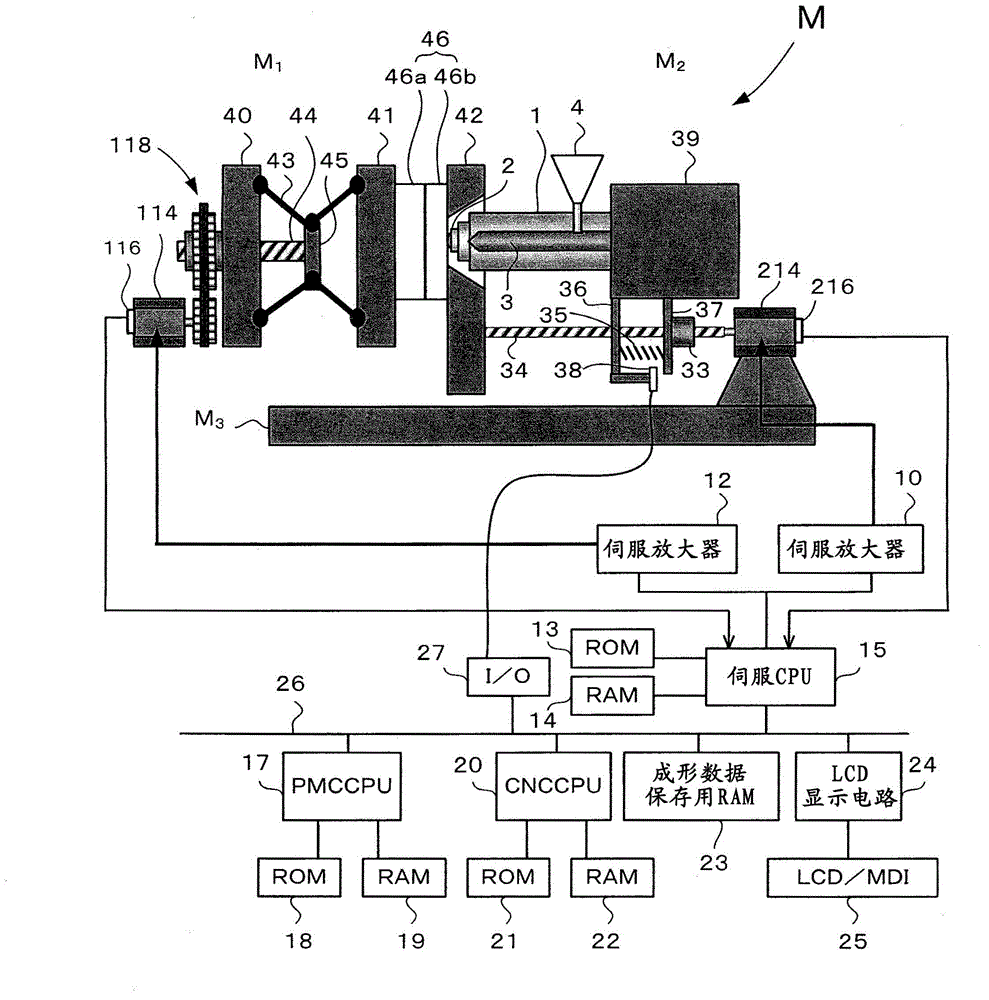
[0022] use figure 1 An injection molding machine to which the nozzle contact control device of the present invention is applied will be described.

[0023] Injection molding machine M on machine base M 3 Clamping part M on top 1 and the injection part M 2 . Injection Department M 2 The resin material (powder) is heated and melted, and the melted resin is injected into the cavity of the mold 46 . A nozzle 2 is attached to the front end of the injection cylinder 1 . A screw 3 is inserted into the injection cylinder 1 . Furthermore, a hopper 4 for supplying a resin material (not shown) into the injection cylinder 1 is attached to the side of the injection cylinder 1 .

[0024] Clamping part M 1 The mold 46 (the movable side mold 46a, the fixed side mold 46b) is opened and closed. The clamping part M 1 Equipped with: a fixed platen 42 on which the fixed side mold 46a is mounted; a movable platen 41 on which the movable side mold 46a is mounted so as to face the fixed si...


PUM


Abstract

The invention relates to a contact controller for the nozzle of an injection molding machine, which comprises a servo motor used for advancing or retreating a nozzle for driving an injection unit to move forwards. A transmission mechanism used for converting the rotational movement of the servo motor into the linear movement of the servo motor is connected with an elastic member for generating a nozzle contact force, wherein a spring or the like is adopted as the elastic member. Meanwhile, when the injection unit and the nozzle are driven to move forwards by means of the servo motor, the nozzle is in contact with a die. Meanwhile, the elastic member starts to deform. The deformation of the elastic member is detected by a sensor and the position of the servo motor for the nozzle during detection is displayed.

Description

technical field [0001] The present invention relates to a nozzle contact control device for an injection molding machine that moves an injection unit forward by a servo motor to generate a predetermined nozzle contact force. Background technique [0002] Injection molding machines include a mold clamping unit and an injection unit. During injection molding operations other than resin ejection, the nozzle of the injection unit is generally in contact with the fixed side mold to maintain a state where a predetermined nozzle contact force is generated against the mold. However, if the continuous molding operation is performed with the nozzle in contact with the mold, the heat at the tip of the nozzle is taken away by the mold, so after the metering process is completed, the process of separating the nozzle from the mold is called sprue break ( spulbreik) action. [0003] The sprue break also has the effect that the sprue is cut between the nozzle and the mold by the retraction...

Claims


Application Information

Patent Timeline
Patent Type & Authority Patents(China)
IPC IPC(8): B29C45/76
CPCB29C45/1777
Inventor 内山辰宏丸山淳平
Owner FANUC LTD
Why Eureka
Try Eureka