Single gearbox front and rear four-wheel drive tractors
A four-wheel drive and gearbox technology, applied in the field of tractors, can solve the problems of unavailable front-wheel drive mode and small application range, and achieve the effects of small investment, simple manufacture and high versatility
- Summary
- Abstract
- Description
- Claims
- Application Information
AI Technical Summary
Problems solved by technology
Method used
Image
Examples
Embodiment 1
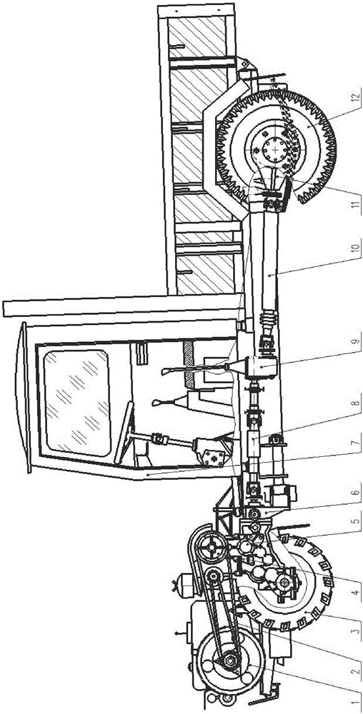
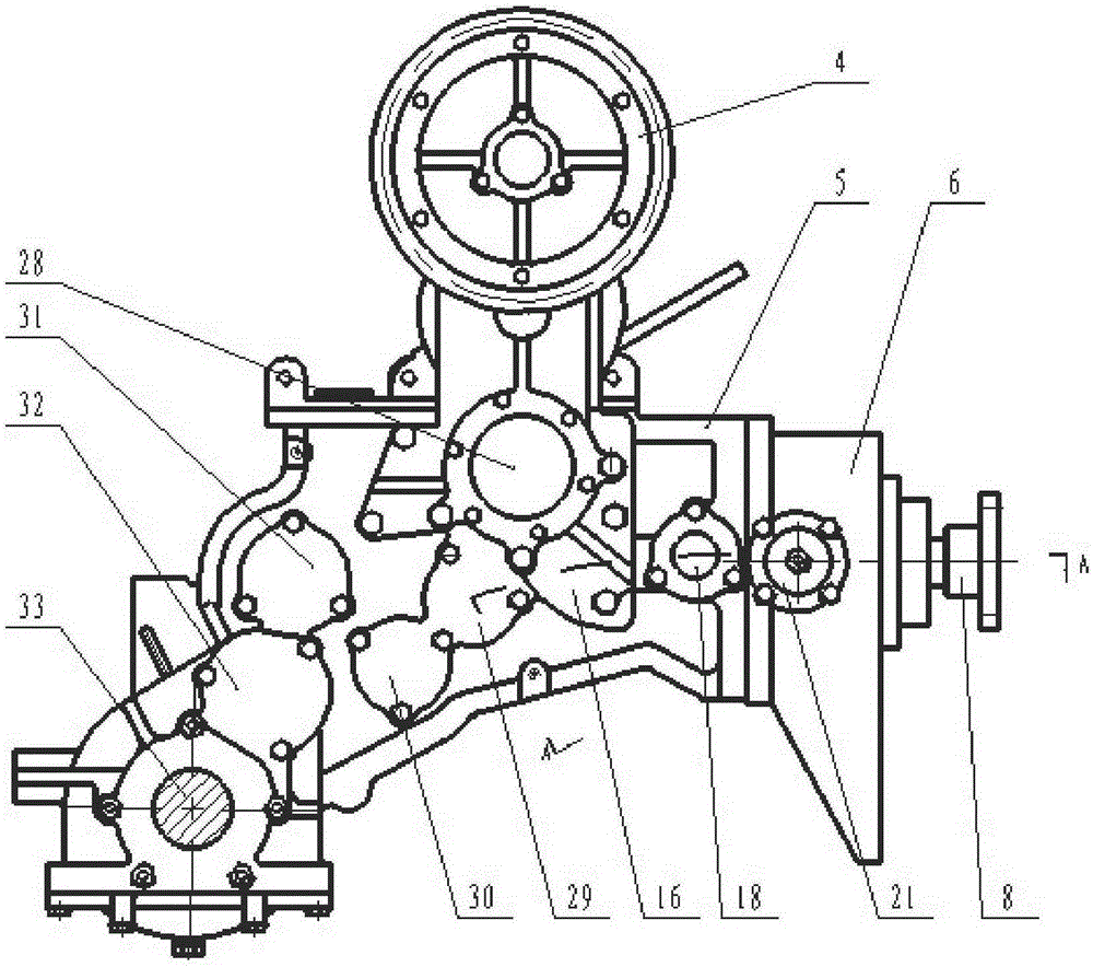
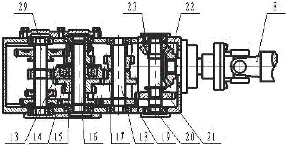
[0024] As shown in the figure, the present invention includes a vehicle body 7, a front wheel 3 installed at the front portion of the vehicle body 7, a rear wheel 12 installed at the rear portion of the vehicle body 7, an engine 1, a V-belt 2, Clutch 4, gearbox 5, transfer case 6, front transmission shaft 8, separation box 9, rear transmission shaft 10, rear drive axle package 11, described gearbox 5 includes I shaft 28, II shaft 16 that transmit power in sequence , III axis 29, IV axis 30, V axis 31, VI axis 32, VII axis 33 and transmission gears on each axis thereof, described gearbox 5 is also provided with VIII axis 18, and VIII axis 18 is provided with switching gear 17 meshes with the synchronous output gear 13 or constant speed output gear 15 installed on the II shaft 16, the synchronous output gear 13 is connected with the II shaft 16 through the bearing 14, and the switching gear 17 is located in the middle of the VIII shaft 18 One end of the VIII shaft 18 is also pro...
Embodiment 2
[0028] The difference from Embodiment 1 is that the power is transmitted from the I shaft 28 to the VII shaft 33 and the front wheel 3 through the shift fork engaging the synchronous output gear 13 and cutting off the engagement of the constant speed output gear 15, and at the same time the power is transmitted from the III shaft 29 through the synchronous output Gear 13 is transmitted to switching gear 17, VIII shaft 18, rear output gear 19, driven gear 20, rear drive output shaft 21, transmission bevel gear 23, driven bevel gear 22, front transmission shaft 8, separation gear 27, upper shaft 26, driven gear 25, lower shaft 24, rear transmission shaft 10, rear drive axle bag 11, rear wheel 12, realize front-wheel, rear wheel gear synchronous drive.
[0029] In the present embodiment, the separation gear 27 of the separation box 9 is meshed with the driven gear 25, and the separation box 9 has no gear position change, and the gear change can be completed only by changing the ge...
Embodiment 3
[0031] Any difference from Embodiment 1-2 is that the meshing of the synchronous output gear 13 is cut off by the shift fork and the connection of the meshing constant speed output gear 15 and the switching gear 17, and the power is transmitted to the VIII shaft 18, the rear output gear 19, from Driven gear 20, rear drive output shaft 21, transmission bevel gear 23, driven bevel gear 22, front drive shaft 8, separation gear 27, upper shaft 26, driven gear 25, lower shaft 24, rear drive shaft 10, rear drive axle Bag 11, trailing wheel 12, realize trailing wheel drives separately.
[0032] In this embodiment, the separation gear 27 of the separation box 9 is meshed with the driven gear 25, and the separation box 9 has no gear change, and the gear change can be completed only by changing the gear of the gearbox 5.
PUM
 Abstract
Description
Claims
Application Information
 - R&D
- Intellectual Property
- Life Sciences
- Materials
- Tech Scout
- Unparalleled Data Quality
- Higher Quality Content
- 60% Fewer Hallucinations
Browse by: Latest US Patents, China's latest patents, Technical Efficacy Thesaurus, Application Domain, Technology Topic, Popular Technical Reports.
© 2025 PatSnap. All rights reserved.Legal|Privacy policy|Modern Slavery Act Transparency Statement|Sitemap|About US| Contact US: help@patsnap.com


