Wiper blade assembly

A wiper and component technology, applied in the field of wiper components, to achieve the effect of preventing lift and vibration

Inactive Publication Date: 2013-03-27
KB WIPER SYST CO LTD
View PDF6 Cites 29 Cited by
  • Summary
  • Abstract
  • Description
  • Claims
  • Application Information

AI Technical Summary

Problems solved by technology

[0006] That is, conventional driving arms for vehicles are roughly classified into a U-shaped clip type with a hook structure, a bayonet type inserted in a plug form, and a sleeve formed by forming a protrusion on the side and using the protrusion. The pin type of embedded structure, the side hole type of the method of inserting and combining from the side of the wiper device developed by Bosch, and the method of combining with the structure surrounded from the upper side of the wiper device Top Lock (Top Lock) type, etc., because of the different shapes and sizes of these various drive arms, there is a restriction that only dedicated wiper devices can be used.

Method used


Image

  • Wiper blade assembly
  • Wiper blade assembly
  • Wiper blade assembly

Examples


no. 1 Embodiment

[0106] Figure 10a It is a perspective view which shows the 1st Example of the adapter part of the wiper blade of this invention.

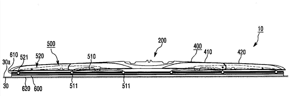
[0107] Such as Figure 10a As shown, the adapter portion 200 of the present invention includes a central portion 212 and a pair of angled end portions 232 . The central portion 212 may include an insertion groove 222 formed in the center of the central portion 212 and connected to the connector 300 , and a first receiving groove 223 and a second receiving groove 224 adjacent to the lower end of the connector 300 .

[0108] The adapter part 200 is formed in a recessed part 242 substantially located at the center of the cover part 400 to connect the chuck part 412 . Preferably, the recessed portion 242 is in the shape of a trapezoid whose width narrows toward the wiper blade 600 , so that the finned portion 415a of the connecting clamp portion 415a as a part of the central finned portion 415 of the wiper blade can be aligned with the lower end por...

no. 2 Embodiment

[0118] Figure 11a It is a perspective view which shows the 2nd Example of the adapter part of the wiper blade of this invention.

[0119] Such as Figure 11a As shown, the adapter part 201 is formed in the center of the cover part and includes an insertion slot 220 connected with the connector 300 .

[0120] The adapter part 201 is formed in a recessed part 240 located substantially in the center of the connecting chuck part 412 of the cover part 400 . Preferably, the recessed portion 240 is formed in a trapezoidal shape whose width narrows toward the wiper blade 600 , so that the fin portion 415 a of the connection clamp portion 415 a that is a part of the central fin portion 415 of the wiper blade can be aligned with the lower end portion of the clamp portion 412 . Connected morphogenesis. However, the form of the recessed portion 240 is not limited to a trapezoidal shape, and may also be formed in a U-shaped form. In this embodiment, the adapter part 201 does not need ...

no. 3 Embodiment

[0131] Figure 12a and Figure 12b It is a perspective view which shows the 3rd Example of the adapter part of the wiper blade of this invention.

[0132] Such as Figure 12a As shown, the adapter part 202 is formed in the recessed part 241 located approximately in the center of the connecting chuck part 412 of the cover part 400 . Preferably, the recessed portion 241 is formed in a trapezoidal shape whose width becomes narrower toward the wiper blade 600 , and the finned portion 415 a of the connecting clamp portion 415 a that is a part of the central finned portion 415 of the wiper blade can be connected with the lower end portion of the clamping portion 412 . Connected morphogenesis. However, the form of the recessed portion 241 is not limited to a trapezoidal shape, and may be formed in a U-shaped form. The adapter part 202 is formed such that its lower surface fits into the recessed part 241 .

[0133] Since the adapter part 202 is integrally formed with the cover pa...


PUM


Abstract

The invention provides a wiper blade assembly, and particularly relates to a wiper blade assembly advantageous in that, when a vehicle runs at a high speed, lifting and chattering of a wiper blade can be prevented, so that stable wiping can be performed. In addition, the invention provides a wiper blade assembly comprising an adapter part capable of coupling with various wiper arms.

Description

technical field [0001] The present invention relates to a wiper assembly, and more particularly to a wiper assembly equipped with a wiper and a connector combined with a wiper arm of an automobile. Background technique [0002] Generally speaking, the wiper is used to remove foreign objects or rain and snow while the car is running, so as to prevent the driver from obstructing the driver's front view. [0003] The existing wiper includes a support rod assembly composed of support rods connected with metal materials in the shape of a single wiper. As for the support rod assembly, a plurality of single-elimination windshield support rods bend the wiper blade mounted with the back plate to conform to the curvature of the car glass. [0004] This kind of wiper has the problem of lifting or chattering under the air pressure acting on the glass surface when the car is running at high speed. [0005] In addition, conventional wiper blades are marketed as dedicated products corres...

Claims


Application Information

Patent Timeline
Patent Type & Authority Applications(China)
IPC IPC(8): B60S1/04B60S1/34
CPCB60S1/4003B60S1/38B60S2001/4054B60S2001/4058B60S1/3806B60S1/40B60S1/4019B60S1/3801B60S2001/3815
Inventor 金兑庆金冠熙安在赫
Owner KB WIPER SYST CO LTD
Why Eureka
Try Eureka