
Lighting system and control method thereof

A technology of a lighting device and a control method, which is applied to the lighting device, the parts of the lighting device, lighting and heating equipment, etc., can solve the problem that the luminous color cannot be obtained again.

Inactive Publication Date: 2013-03-27
TOSHIBA LIGHTING & TECH CORP
View PDF6 Cites 7 Cited by
  • Summary
  • Abstract
  • Description
  • Claims
  • Application Information

AI Technical Summary

Problems solved by technology

[0003] However, in the conventional color-changing LED lighting device, even if the required luminous color is set by the operation of the rotary table, it is still possible that the same luminous color as the desired luminous color cannot be obtained again after setting other luminous colors.

Method used


Image

  • Lighting system and control method thereof
  • Lighting system and control method thereof
  • Lighting system and control method thereof

Examples


example 1

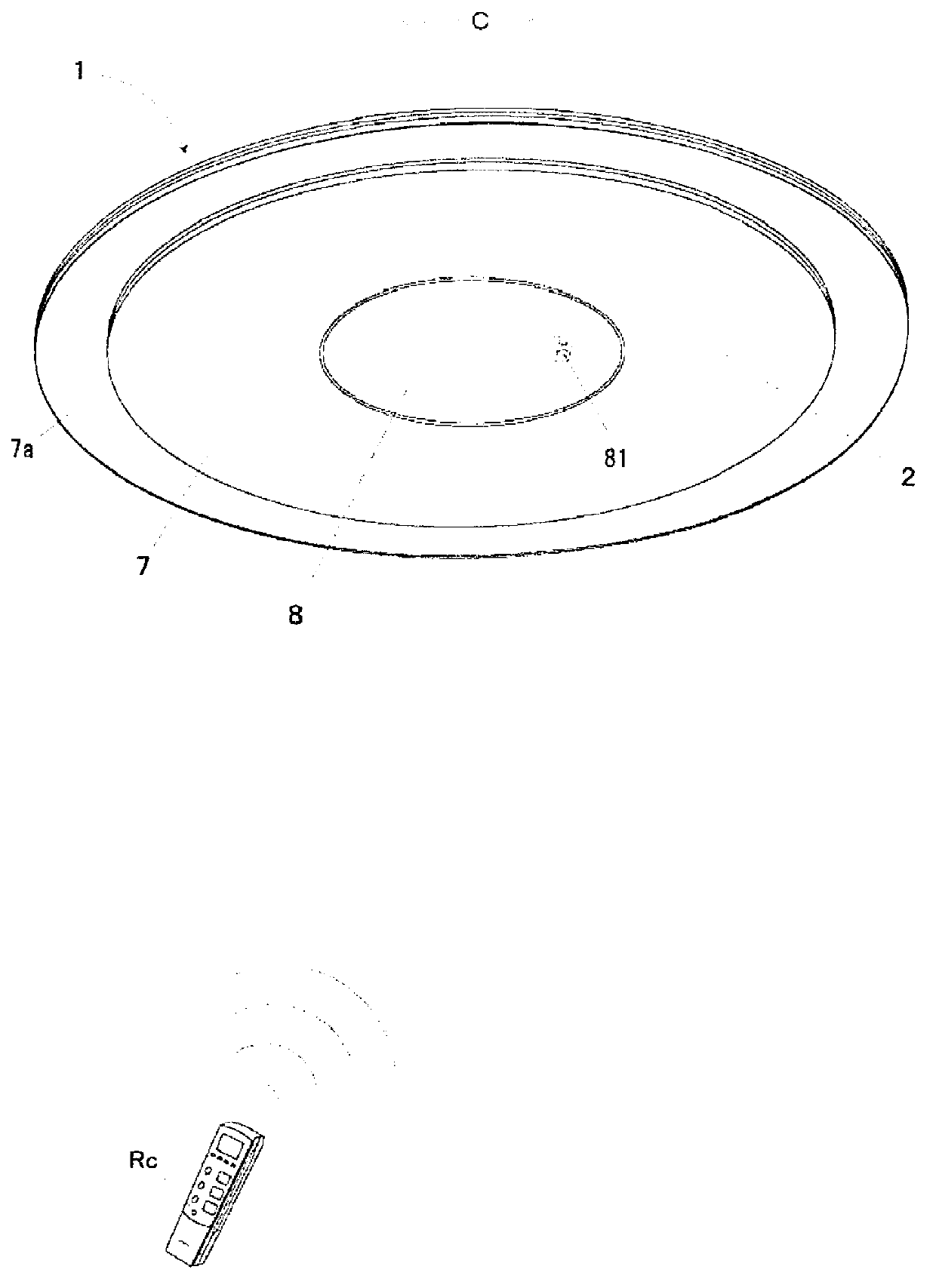
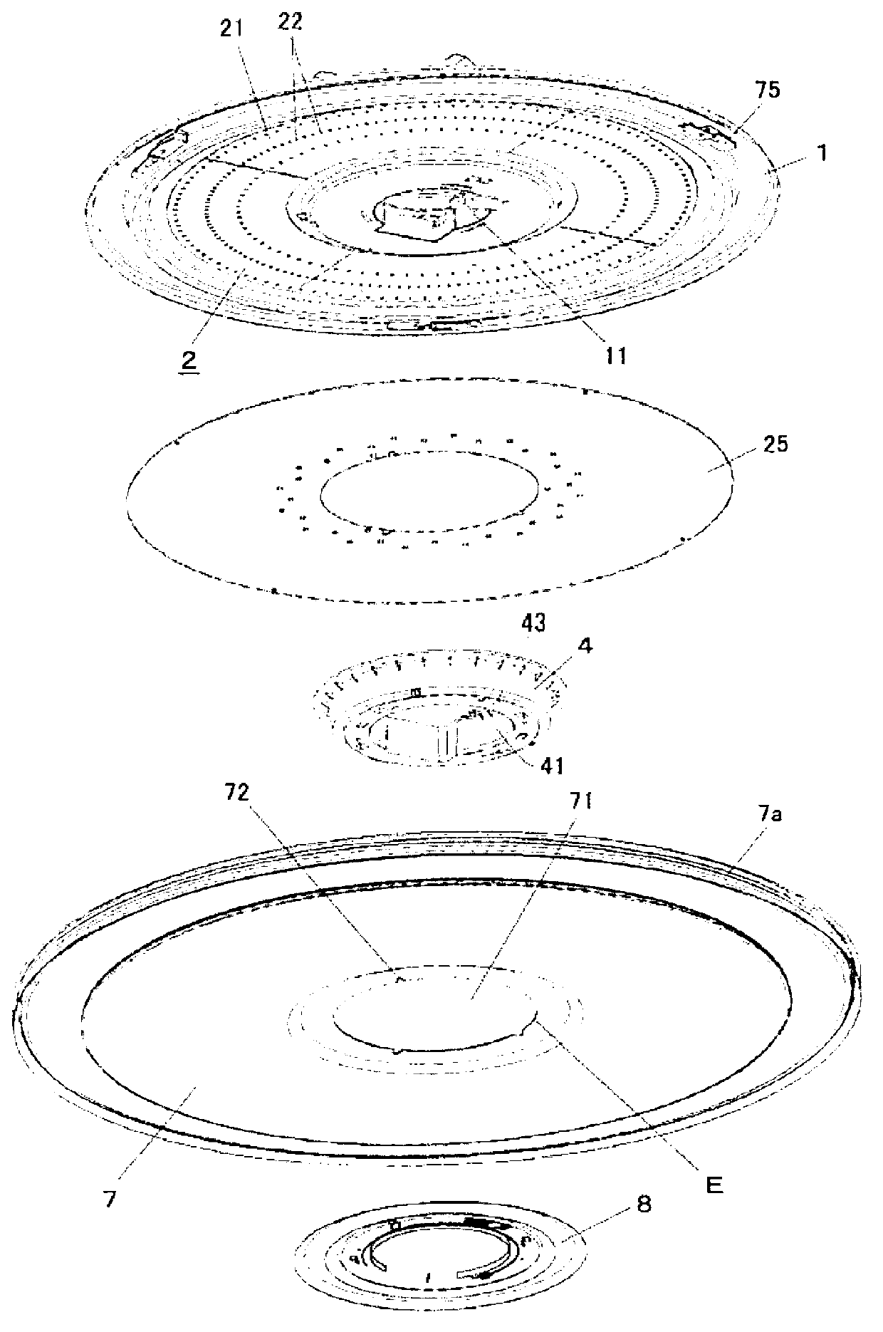
[0107] The lighting device of Example 1a includes: a first light source having a predetermined color temperature; a second light source having a color temperature different from that of the first light source; a first lighting circuit for lighting the first light source; a second lighting circuit for lighting the second light source Lighting is performed; the signal input unit inputs an external signal; The first signal input from the signal input unit controls the first and second lighting circuits to start lighting control based on the first and second light source lighting control cycles, and controls the first and second lighting circuits according to the second signal input to the signal input unit. The second lighting circuit stops the lighting control based on the lighting control cycle of the first and second light sources.

[0108] The lighting device according to the embodiment of Example 1b is the lighting device according to Example 1a, wherein the control circuit ...

example 2

[0247] The lighting device of Example 2a includes: a first light source emitting light with a half-value width of 100 nm or more; a second light source emitting light with a half-value width of less than 100 nm; a first lighting circuit for lighting the first light source; a second lighting circuit , lighting the second light source; a light sensor; and a control circuit that controls the lighting of the first lighting circuit based on the detection value of the light sensor, and lights the second lighting circuit based on a predetermined value when the light sensor is in operation. control.

[0248] The lighting device of Example 2b is the lighting device according to Example 2a, characterized in that the control circuit has a first control circuit and a second control circuit, the first control circuit is connected to the light sensor and controls the lighting of the first lighting circuit, so The second control circuit controls the lighting of the second lighting circuit. ...

example 3

[0266] The lighting device of Example 3a includes: a first light source emitting light with a half-value width of 100 nm or more; a second light source emitting light with a half-value width of less than 100 nm; a first lighting circuit for lighting the first light source; a second lighting circuit , lighting the second light source; a first light sensor; a second light sensor having a sensitivity peak at a wavelength different from that of the first light sensor; and a control circuit based on a detection value of the first light sensor or the second light sensor The lighting control of the first lighting circuit is performed, and the lighting control of the second lighting circuit is performed based on the detection values ​​of the first light sensor and the second light sensor.

[0267] The lighting device of Example 3b is the lighting device according to Example 3a, characterized in that the control circuit has a first control circuit and a second control circuit, the first...


PUM


Abstract

The invention provides a lighting system and a control method thereof, which enables easy obtaining prescribed light source colors, and easy reproduce the prescribed light source colors. A lighting system according to embodiments includes a light element (22R, 22G, and 22B), a lighting circuit (104, 105, and 106), a remote control signal input unit (25 a), and a control circuit. Red, green and blue light sources lighting control circulation. The lighting circuits (104, 105, and 106) are instructed by a first signal inputed by a remote control signal receiving portion (25a), to start out lighting control of the lighting control circulation based on the red, green and blue light sources, and stops the lighting control circulation of the red, green and blue light sources according to the second signal inputted by the lighting circuits (104, 105, and 106).

Description

technical field [0001] Embodiments of the present invention relate to a lighting device and a control method thereof. Background technique [0002] In conventional color-changing LED lighting devices equipped with a plurality of light emitting diodes (Light Emitting Diodes, LEDs) with different light emitting colors, in order to change the color of the light source of the lighting device in a compact and simple manner, each light emitting diode is installed correspondingly and relative to the lighting. The light output of each light emitting diode is set by the rotation angle of the turntable provided rotatably by the apparatus main body, and each light emitting diode is turned on with the set light output. [0003] However, in the conventional color-changing LED lighting device, even if the required luminous color is set by the operation of the rotary table, it is still possible that the same luminous color as the desired luminous color cannot be obtained again after settin...

Claims


Application Information

Patent Timeline
Patent Type & Authority Applications(China)
IPC IPC(8): F21S2/00F21V23/00H05B37/02F21Y101/02H05B44/00
CPCH05B37/0272F21V7/00H05B33/086H05B47/195H05B45/375H05B45/22H05B45/20H05B31/50
Inventor 石北彻岩井直子河野诚菅飞吕也小和田贵勇甲佐清辉河野仁志斋藤阳介
Owner TOSHIBA LIGHTING & TECH CORP
Features
  • Generate Ideas
  • Intellectual Property
  • Life Sciences
  • Materials
  • Tech Scout
  • Unparalleled Data Quality
  • Higher Quality Content
  • 60% Fewer Hallucinations
Learn More