Air conditioning compressor exhaust energy recovery and utilization method

An air-conditioning compressor, compressor technology, applied in the direction of compressors, ventilation and heating energy recovery systems, irreversible cycle compressors, etc., to achieve the effect of improving refrigeration or heating capacity and improving air conditioning efficiency

Inactive Publication Date: 2013-03-27
张育仁
View PDF6 Cites 3 Cited by
  • Summary
  • Abstract
  • Description
  • Claims
  • Application Information

AI Technical Summary

Problems solved by technology

[0003] The purpose of the present invention is to solve the above problems, and to provide a method for recovering and utilizing the outlet energy of the air conditioner compressor. By using the method of the present invention, this part of energy can be effectively recovered without consuming any additional energy. make full use of the recovered energy

Method used


Image

  • Air conditioning compressor exhaust energy recovery and utilization method
  • Air conditioning compressor exhaust energy recovery and utilization method
  • Air conditioning compressor exhaust energy recovery and utilization method

Examples


Embodiment 1

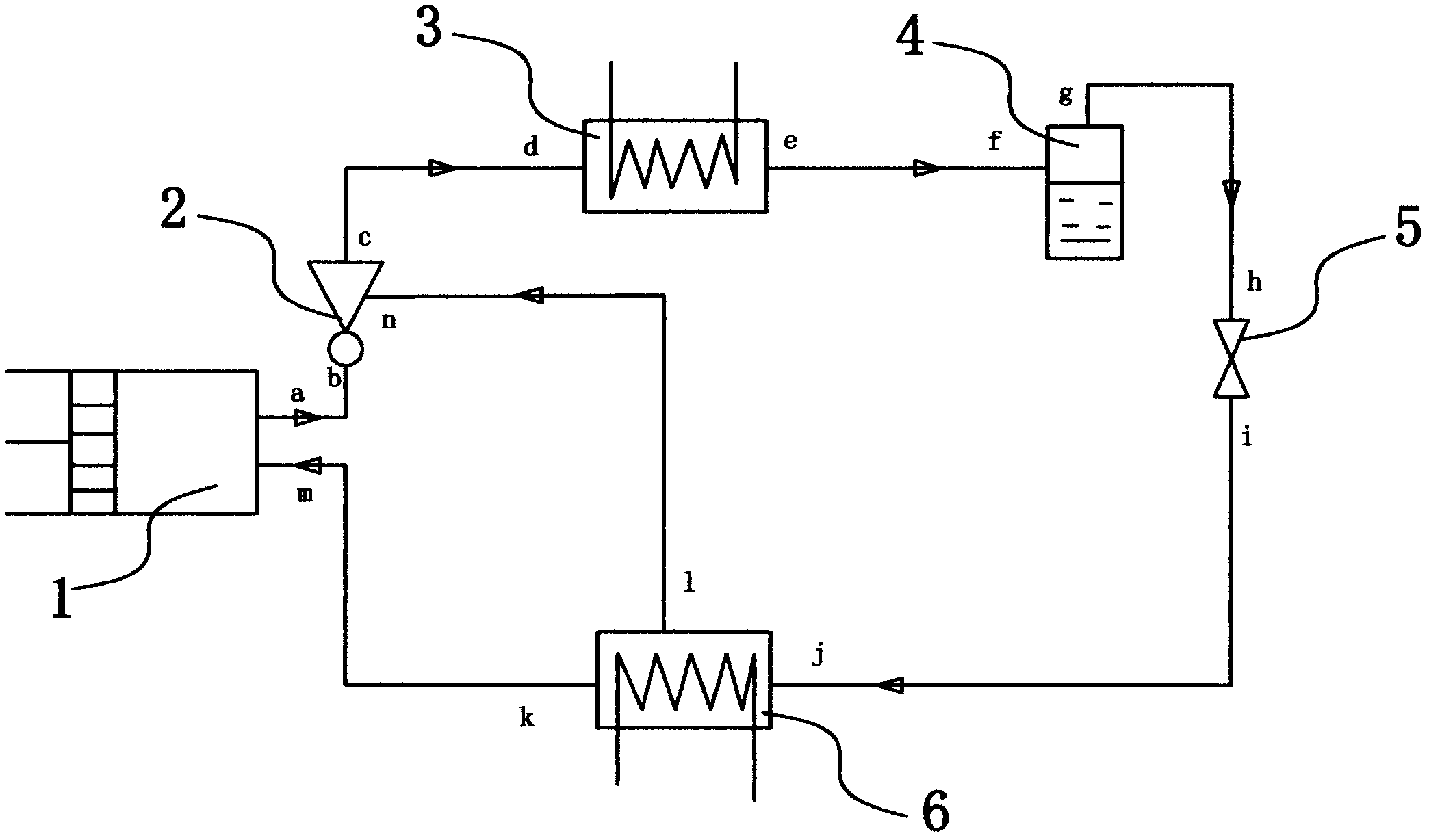
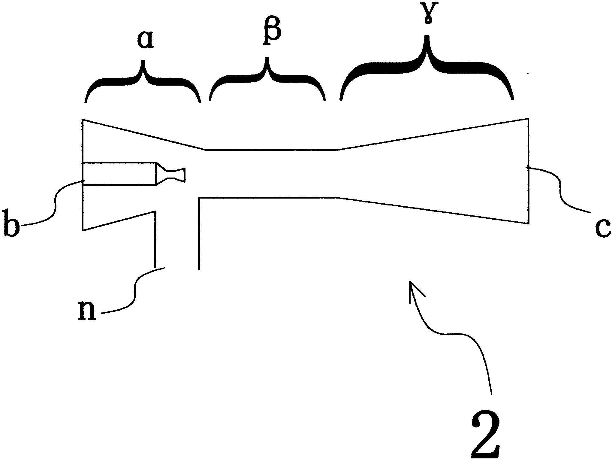
[0027] Such as figure 1 As shown, the outlet a of the compressor 1 in the figure and the ejector 2 ( figure 2 It is the structural diagram of the injector, which includes the introduction section α, the mixing section β and the diffusion and boosting section γ. The left side of the figure is the inlet b of the injector, which is the inlet port of the working fluid; the right side is the outlet c of the injector , which is used as the outlet port of the mixed fluid; the lower side is the diversion inlet n of the injector, which is used as the inlet port of the introduced fluid) and the inlet b is connected, so that the high-pressure and high-temperature medium fluid at the outlet a of the compressor becomes the working fluid of the injector, Enter the ejector from the inlet b; connect the outlet c of the ejector 2 to the inlet d of the condenser 3 of the air conditioning system, so that the working fluid and the injection fluid are mixed, diffused and pressurized and then ente...

Embodiment 2

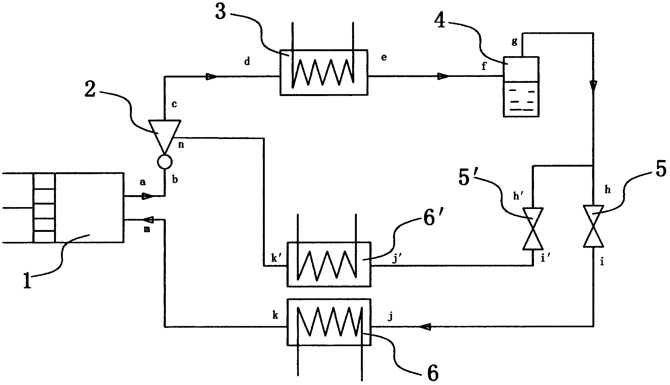
[0030] see image 3 , connecting the outlet a of the compressor 1 in the figure with the ejector 2 ( figure 2 Inlet b of the injector structure diagram) is connected, so that the high-pressure and high-temperature medium at the outlet a of the compressor becomes the working fluid of the injector, and enters the injector from the inlet b of the injector; the outlet c of the injector 2 is connected with the air-conditioning system The inlet d of the condenser 3 is connected so that the working fluid and the injection fluid are mixed, diffused and pressurized and then enter the condenser 3 from the inlet d of the condenser; the outlet e of the condenser 3 is connected with the inlet f of the air-water separator 4 of the air conditioning system Connected, the filtered medium flow comes out from the outlet g of the gas-water separator and enters the inlet h of the throttle valve 5 and the inlet h' of the throttle valve 5' of the air-conditioning system respectively, and the thrott...


PUM


Abstract

The invention discloses an air conditioning compressor exhaust energy recovery and utilization method which adopts the scheme that an ejector is installed between a compressor and a condenser of an air conditioning system; the inlet of the ejector is connected with the outlet of the compressor; the outlet of the ejector is connected with the inlet of the condenser; and the drainage inlet of the ejector is connected with an evaporator of the air conditioning system. The air conditioning compressor exhaust energy recovery and utilization method has the beneficial effects that the air conditioning efficiency is improved by above 30% while no energy is consumed, or the refrigerating capacity or heating capacity is greatly improved under the condition of the same power consumption.

Description

technical field [0001] The invention belongs to the field of refrigeration and heating, ventilating and air-conditioning, and relates to a technical method for energy recovery and reuse of an air-conditioning compression cycle system, in particular to a method for recovering and utilizing outlet energy of an air-conditioning compressor. Background technique [0002] The air conditioning system is mainly composed of a throttle valve, an evaporator, a condenser, and a compressor. The compressor is connected in series with the condenser, throttle valve, and evaporator to form an air conditioning system. The machine consumes electric energy, which converts electric energy into pressure energy, so that the medium fluid changes from liquid to gas in the evaporator and absorbs heat. When the medium fluid is compressed by the compressor and leaves the compressor, it has high-pressure and high-temperature energy. The condenser cools down, causing the medium to change from a gaseous s...

Claims


Application Information

Patent Timeline
Patent Type & Authority Applications(China)
IPC IPC(8): F24F12/00F25B9/08F24F13/30F25B41/04
CPCF25B1/10F25B9/08F24F12/00F25B5/02F24F13/30F25B41/04F25B1/06F25B2341/001F25B2341/0015
Inventor 张育仁
Owner 张育仁
Why Eureka
Try Eureka