Refrigerator

A technology of refrigerators and refrigerants, applied in household refrigerators, household refrigeration devices, defrosting, etc., can solve the problems of longer defrosting time, cooler temperature difference, and ineffective melting, etc., and achieve high energy-saving performance Effect

Inactive Publication Date: 2013-03-27
HITACHI APPLIANCES INC
View PDF8 Cites 5 Cited by
  • Summary
  • Abstract
  • Description
  • Claims
  • Application Information

AI Technical Summary

Problems solved by technology

[0007] However, in the prior art of Patent Document 1, since the refrigerant does not flow into the cooler when the defrosting heater is energized, the increase in the temperature of the cooler caused by the refrigerant inflow is suppressed, and the defrosting time becomes longer, and more energy is consumed. more electricity
[0008] In addition, in the case where there is a defrosting heater in the lower part of the cooler shown in Patent Document 1, since the defrosting heater is sequentially heated from the lower part of the cooler, a temperature difference occurs between the upper part and the lower part of the cooler, and it cannot be effectively melted. Frost clinging to the cooler

Method used


Image

  • Refrigerator
  • Refrigerator
  • Refrigerator

Examples


Embodiment 1

[0069] Second, refer to Image 6 The refrigeration cycle of Example 1 will be described. Image 6 It is a schematic diagram showing the refrigerant flow path of a refrigerator.

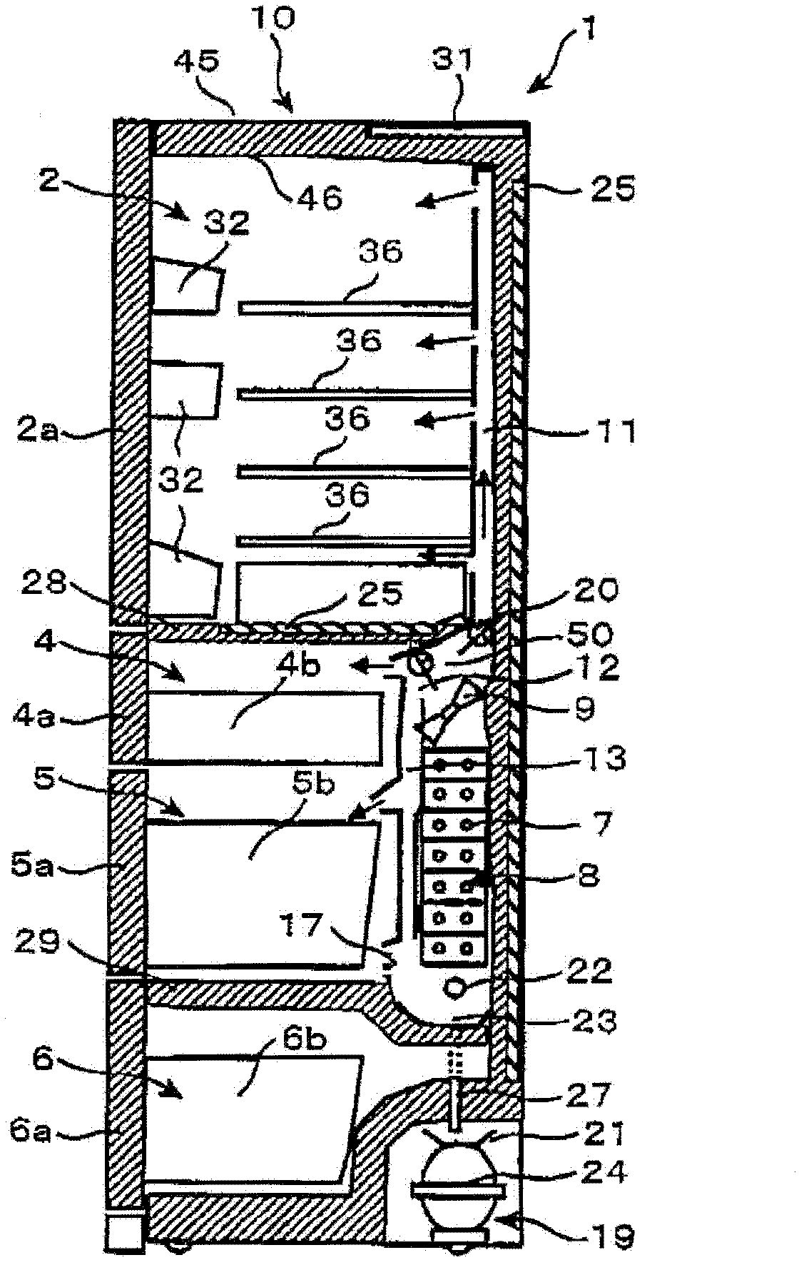
[0070] Image 6 Among them, 24 is the compressor for compressing the refrigerant in the refrigeration cycle, which is set at figure 2 In the shown machine chamber 19, the rotational speed is controlled by the control board 31 so that it can be changed. 52 is a condensing mechanism for condensing the refrigerant compressed by the compressor 24 .

[0071] The condensing mechanism 52 is composed of a condenser 52a arranged in the machine room 19 to condense the refrigerant compressed by the compressor 24, a heat radiation pipe 52b which condenses the refrigerant and prevents condensation on the side of the refrigerator 1, and condenses the refrigerant and prevents the partition 57 from condensing. Exposed heat pipe 52c constitutes. Also, the partition 57 for disposing the radiating pipe 52c, such a...

Embodiment 2

[0089] Second, refer to Figure 9 The refrigeration cycle of Example 2 will be described. Figure 9 It is a schematic diagram showing the refrigerant flow path of a refrigerator.

[0090] Indicated at 55 is a connection pipe (second refrigerant flow path) connecting the radiation pipe 52b and the decompression device 58 . Indicated at 54 is a refrigerant valve (first refrigerant flow adjustment mechanism) for blocking or switching the radiation pipe 52c (first refrigerant flow path) and the connecting pipe 55 (second refrigerant flow path). 56 is a check valve provided at the outlet of the refrigerant passage (the outlet of the heat radiation pipe 52c (first refrigerant passage)) to prevent refrigerant from entering between the refrigerant passage of the heat radiation pipe 52c and the connecting pipe 55 . Since other symbols are the same as those in Embodiment 1, the same symbols are assigned and descriptions thereof are omitted.

[0091] The control mechanism at the time ...

Embodiment 3

[0104] Second, refer to Figure 12 The refrigeration cycle of Example 3 will be described.

[0105] exist Figure 12 Among them, 54a is a refrigerant valve (the first refrigerant flow path adjustment mechanism) that blocks or switches the radiating pipe 52c and the connecting pipe 55, and 54b is a refrigerant valve that blocks the refrigerant flow path to the decompression device 58 (second refrigerant flow path adjustment mechanism). agent channel adjustment mechanism), the decompression device 58 decompresses the refrigerant condensed by the condensing mechanism. The other symbols are the same as those in Example 1, and description thereof will be omitted.

[0106] The control mechanism at the time of defrosting in the third embodiment will be described. Figure 13 It is a timing chart showing the states of the compressor, the defrosting heater, the first refrigerant flow path adjustment mechanism, and the second refrigerant flow path adjustment mechanism during defrostin...


PUM


Abstract

The present invention relates to a refrigerator, and aims at enabling the temperature of a cooler to rise uniformly by controlling refrigerant flowing into the cooler during defrosting, thereby obtaining the refrigerator with a high electricity saving performance. The refrigerator comprises: a compressor used for compressing the refrigerant; a condenser used for condensing the refrigerant compressed by the compressor; a decompressor used for performing decompression for the refrigerant condensed by the condenser; the cooler used for vaporing the refrigerant decompressed by the decompressor; a heating mechanism used for heating the cooler; and a refrigerant flow path adjusting mechanism used for blocking a refrigerant flow path. The refrigerator is characterized in that during defrosting operation of the cooler, the refrigerant flow path is blocked through the refrigerant flow path adjusting mechanism, so that the compressor stops, when the cooler is heated by the heating mechanism, after preset time or after the cooler reaches a preset temperature, the refrigerant flow path is opened.

Description

technical field [0001] The present invention relates to refrigerators. Background technique [0002] There is Japanese Patent No. 4341215 (Patent Document 1) as a prior art for controlling a refrigerant flow path during defrosting. [0003] Patent Document 1 discloses the following technology, comprising: a compressor for compressing the refrigerant; a condenser for condensing the refrigerant compressed by the compressor; A decompression device for decompressing the refrigerant; a cooler for evaporating the refrigerant decompressed by the decompression device; a liquid receiver for storing the remaining liquid refrigerant flowing out of the above cooler; connected to the above liquid storage in sequence A refrigerating cycle constituted by a suction pipe connected to the compressor; a defrosting heater for melting frost adhering to the cooler; During the defrosting operation of defrosting, the control mechanism that completely closes the above-mentioned decompression devic...

Claims


Application Information

Patent Timeline
Patent Type & Authority Applications(China)
IPC IPC(8): F25D11/00F25D23/00
CPCF25B49/022F25D17/065F25B2600/0251F25D21/08F25D29/00F25D17/045F25B41/20Y02B40/00
Inventor 藤木义明冈留慎一郎
Owner HITACHI APPLIANCES INC
Why Eureka
Try Eureka