Single-stage direct actuating low-voltage permanent magnet vacuum load switch

A technology of load switch and permanent magnet vacuum, applied in high-voltage/high-current switches, electric switches, high-voltage air circuit breakers, etc., can solve the problems of power loss, unfavorable integrated design of complete sets of products, large switch space, etc., to reduce Loss of electrical energy, favorable for integrated design, low failure rate

A technology of load switch and permanent magnet vacuum, applied in high-voltage/high-current switches, electric switches, high-voltage air circuit breakers, etc., can solve the problems of power loss, unfavorable integrated design of complete sets of products, large switch space, etc., to reduce Loss of electrical energy, favorable for integrated design, low failure rate

CN103000443BActive Publication Date: 2015-06-17北京博瑞莱智能科技集团有限公司

Image

  • Single-stage direct actuating low-voltage permanent magnet vacuum load switch
  • Single-stage direct actuating low-voltage permanent magnet vacuum load switch

Examples


Embodiment Construction

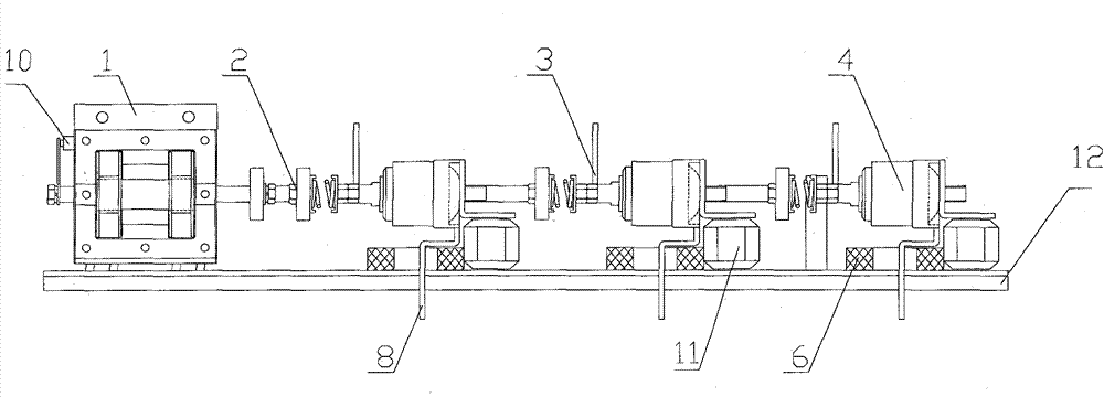
[0016] The single-stage direct-acting low-voltage permanent magnet vacuum load switch of the present invention will be further described below in conjunction with the accompanying drawings.

[0017] See attached Figure 1-2 As shown, a single-stage direct-acting low-voltage permanent magnet vacuum load switch according to the present invention includes a base 12, a permanent magnet operating mechanism 1, a low-voltage vacuum interrupter 4 and direct-acting components, and the base 12 is provided with insulation Support 11, limit guide sleeve 5, the permanent magnet operating mechanism 1 is fixed on the base 12, one end of the direct motion assembly is connected to the permanent magnet operating mechanism 1, and one end is connected to the base 12 through the limit guide sleeve 5 The number of the low-voltage vacuum interrupter 4 is preferably three, the static ends of the three low-voltage vacuum interrupter 4 are fixed on the base 12 through the insulating support 11, the mov...


PUM


Abstract

The invention relates to a single-stage direct actuating low-voltage permanent magnet vacuum load switch which comprises a base, a permanent magnet operating mechanism, a low-voltage vacuum arc-extinguishing chamber and a direct actuating component. The permanent magnet operating mechanism is connected to the base. The low-voltage vacuum arc-extinguishing chamber is connected with the base and the permanent magnet operating mechanism through the direct actuating component. The single-stage direct actuating low-voltage permanent magnet vacuum load switch has the advantages that the switch is elongated in overall structure, miniaturization of low-voltage switches is realized, transmission components are simple, reliable and smaller in size, and the switch is suitable for integrated design of equipment in narrow space and complete equipment, especially suitable for being used as a low-voltage load control switch inside a transformer.

Description

technical field [0001] The invention relates to a single-stage direct-acting low-voltage permanent magnet vacuum load switch, in particular to a bar-shaped vacuum arc-extinguishing switch using a permanent magnet operating mechanism for low-voltage load control. Background technique [0002] In the prior art, most of the three-phase low-voltage vacuum switches are frame-type structures, and electromagnetic operating mechanisms are commonly used. This type of switch takes up a lot of space, which is not suitable for occasions with small spaces and is not conducive to the integrated design of complete sets of products. The coil needs to be charged for a long time to maintain the state, so the electric energy is inevitably lost. Contents of the invention [0003] In response to the above needs, the purpose of the present invention is to solve the above technical problems and provide a low-voltage vacuum load control switch with a direct-acting mechanism that has few transmiss...

Claims


Application Information

Patent Timeline
17 Jun 2015
Publication
CN103000443B
IPC
H01H33/666; H01H33/664
Inventors
魏贞祥; 杨福荣