Composite thermal insulation concrete load-bearing wall

A technology of heat-insulating concrete and heat-insulating concrete, applied to walls, building components, buildings, etc., can solve the problems of unsatisfactory comfort and poor overall performance, and achieve the effects of convenient construction, good ductility, and strong horizontal load resistance

Active Publication Date: 2007-01-03
陈信孚 +1
View PDF0 Cites 10 Cited by
  • Summary
  • Abstract
  • Description
  • Claims
  • Application Information

AI Technical Summary

Problems solved by technology

In order to save materials, our country has also invented concrete perforated slab houses. Practice has proved that the overall performance of this house is poor and cannot meet the comfort requirements.

Method used


Image

  • Composite thermal insulation concrete load-bearing wall
  • Composite thermal insulation concrete load-bearing wall
  • Composite thermal insulation concrete load-bearing wall

Examples


Embodiment 1

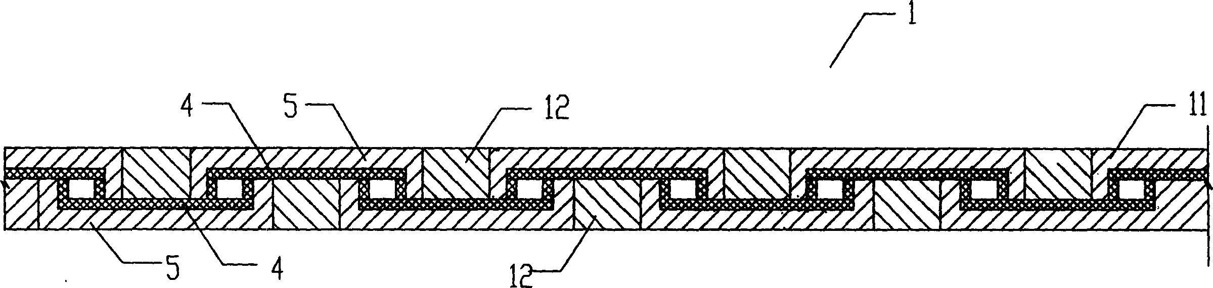
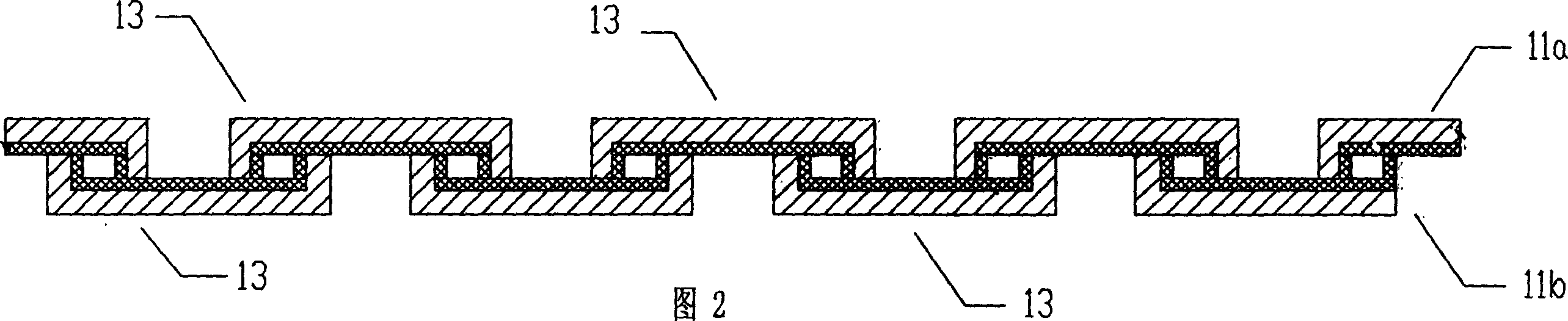
[0024] see figure 1 And Fig. 2, a kind of composite thermal insulation concrete load-bearing wall, comprises wall body 1, connecting beam 2, is provided with two layers of prefabricated thermal insulation concrete wall body 11a, 11b in body of wall 1, prefabricated thermal insulation concrete wall body 11a, 11b is The inner surface is covered with the concrete slab 5 of the thermal insulation material layer 4, and each layer of prefabricated thermal insulation concrete walls 11a, 11b is composed of several groove-shaped or L-shaped prefabricated thermal insulation concrete wall units 13, and two adjacent prefabricated thermal insulation concrete walls on the same floor Between the wall units 13 are cast-in-place concrete wall vertical ribs 12, and the cast-in-place concrete wall vertical ribs 12 connect two adjacent prefabricated thermal insulation concrete wall units 13 on the same floor; The body units 13 are staggered in such a way that the notches are opposite, and the top...


PUM


Abstract

The present invention relates to a concrete load-bearing wall with compound heat-insulating layer. Said load-bearing wall includes wall body and connecting beam. In the wall body of external wall two layers of prefabricated heat-insulating concrete wall bodies are set, said prefabricated heat-insulating concrete wall body is a concrete plate whose external surface is covered with heat-insulating material, every layer of prefabricated heat-insulating concrete wall body is composed of several trough-type or L-shaped prefabricated heat-insulating concrete wall body units. Besides, said invention also provides the concrete assembly and construction method and steps of said compound heat-insulating concrete load-bearing wall.

Description

technical field [0001] The invention relates to a concrete house, in particular to a concrete load-bearing wall with a composite thermal insulation layer. Background technique [0002] Existing low-rise houses and multi-storey houses are mostly masonry houses or concrete frame houses. Small high-rise buildings with a height of no more than 50 meters are mostly concrete buildings. The existing masonry building structure system generally has poor earthquake resistance, and clay bricks are mostly used for building. Extensive use of clay resources will seriously damage farmland and affect the sustainable development of agriculture. Most of the existing concrete houses use cast-in-place concrete structure systems, which consume a lot of wood to make formwork, which will seriously consume forest resources and affect the environment and climate. [0003] Existing masonry houses and cast-in-place concrete house structures are all constructed on site, with high manual labor intens...

Claims


Application Information

Patent Timeline
IPC IPC(8): E04B2/56E04B2/84E04B1/74
Inventor 陈信孚曲萍
Owner 陈信孚
Why Eureka
Try Eureka