Multidirectional rotary connection cable clamp
A cable clamp and rotary connection technology, which is applied in connection, conductive connection, electrical component connection, etc., can solve the problems of easy loosening of screws, short service life, uneven force, etc., and achieve stable and reliable connection, convenient and safe use, The effect of constant clamping force
- Summary
- Abstract
- Description
- Claims
- Application Information
AI Technical Summary
Problems solved by technology
Method used
Image
Examples
Embodiment 1
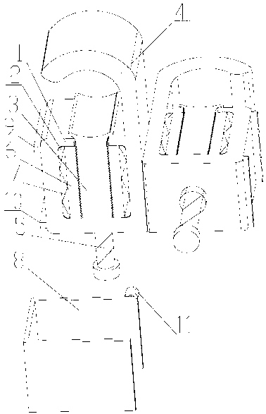
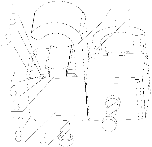
[0020] Such as figure 1 and figure 2 As shown, a multi-directional rotating connection cable clamp is characterized in that it includes two movably connected cable clamps, each cable clamp includes a clamp body 1, and a groove 2 is provided in the clamp body 1, and the concave A moving chuck 3 that can move up and down is embedded in the groove 2. A static chuck 4 opposite to the clamping end of the moving chuck 3 is fixedly connected to the clamp body 1. The opening orientation of the clamp body 1 and the groove 2 is opposite. One side is provided with a bolt hole, and an adjusting bolt 5 passes through the bolt hole and is fixedly connected with the clamp body 1 , and is connected with the movable chuck 3 at the same time. The sizes of the two cable clamps can be the same or different, and can hold cables with the same or different thicknesses. The two movable cable clamps are back-to-back structure, face-to-face structure or back-to-face structure. The back-to-back struc...
Embodiment 2
[0022] On the basis of embodiment 1, this embodiment has been improved as follows:
[0023] One side or both sides of the movable chuck 3 of one of the two movably connected cable clamps is provided with downward check sawtooth, and the outer side of the check sawtooth of the movable clamp 3 is provided with The anti-loosening anti-reversal sawtooth sheet 6 matched with it, at least one side of the anti-loosening anti-reversal sawtooth sheet 6 and the clamp body is provided with a compression spring 7, the movable chuck 3 and the anti-loosening anti-reversal sawtooth sheet 6 Compressed by clip spring 7. Wherein the compression spring 7 is a wave-shaped leaf spring or a columnar spring, and the columnar spring can be a cylindrical helical spring, preferably a leaf spring. The difference from Example 1 when disassembling is that the outer protective cover 8 needs to be disassembled first, the compression spring 7 is taken out, the anti-loosening anti-reverse saw-tooth piece 6 i...
Embodiment 3
[0025] On the basis of embodiment 1, this embodiment has been improved as follows:
[0026] One side or both sides of the movable clamp 3 of each cable clamp of the two movably connected cable clamps are respectively provided with downward check sawtooth, and the outer side of the check sawtooth of the movable clamp 3 is provided with There is an anti-loosening anti-reversal sawtooth sheet 6 matched with it, and a compression spring 7 is arranged between the anti-loosening and anti-reversal sawtooth sheet 6 on at least one side and the clamp body, and the movable chuck 3 and the anti-loosening and anti-reversal sawtooth sheet 6 is compressed by stage clip 7. Wherein the compression spring 7 is a wave-shaped leaf spring or a columnar spring, and the columnar spring can be a cylindrical helical spring, preferably a leaf spring. The difference from Example 1 when disassembling is that the outer protective cover 8 needs to be disassembled first, the compression spring 7 is taken ...
PUM
 Abstract
Description
Claims
Application Information
 - R&D
- Intellectual Property
- Life Sciences
- Materials
- Tech Scout
- Unparalleled Data Quality
- Higher Quality Content
- 60% Fewer Hallucinations
Browse by: Latest US Patents, China's latest patents, Technical Efficacy Thesaurus, Application Domain, Technology Topic, Popular Technical Reports.
© 2025 PatSnap. All rights reserved.Legal|Privacy policy|Modern Slavery Act Transparency Statement|Sitemap|About US| Contact US: help@patsnap.com


