
Cooling sleeve of liquid cooling electric motor

A cooling jacket and liquid cooling technology, applied in the direction of electric components, cooling/ventilation devices, electrical components, etc., to achieve the effects of low production cost, high heat transfer efficiency, and stable coolant distribution

Inactive Publication Date: 2013-03-27
YANTAI DINGLI NEW ENERGY VEHICLE POWER SYST
View PDF11 Cites 12 Cited by
  • Summary
  • Abstract
  • Description
  • Claims
  • Application Information

AI Technical Summary

Problems solved by technology

[0003] Patent WO2003100946 describes some methods to increase the heat transfer area, but the axial coolant flow direction is still used inside the stator

Method used


Image

  • Cooling sleeve of liquid cooling electric motor
  • Cooling sleeve of liquid cooling electric motor
  • Cooling sleeve of liquid cooling electric motor

Examples


Embodiment Construction

[0025] The principles and features of the present invention are described below in conjunction with the accompanying drawings, and the examples given are only used to explain the present invention, and are not intended to limit the scope of the present invention.

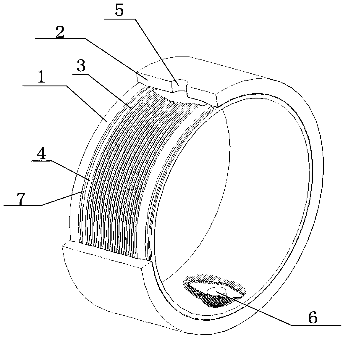
[0026] A cooling jacket for liquid cooling electric motors, such as figure 1 As shown, it includes an inner cooling ring 1 and an outer cooling ring 2, the outer cooling ring 2 is sleeved on the inner cooling ring 1, the inner cooling ring 1 has an inner surface and an outer surface, and is surrounded by the inner surface An inner cavity is formed, and heat sinks 3 are arranged on the outer surface of the inner cooling ring 1, and the heat sinks 3 are arranged in parallel on the outer surface of the inner cooling ring 1, and the adjacent heat sinks 3 A gap is left between them to form a flow channel 4. In order to achieve the best heat transfer effect, it is necessary to maintain a high-speed coolant flow to achieve...


PUM


Abstract

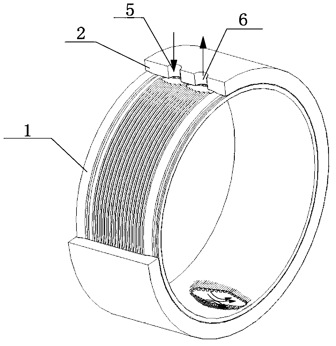
The invention relates to a cooling sleeve of a liquid cooling electric motor. The cooling sleeve comprises an inner cooing ring and an outer cooling ring, the outer cooing ring is sleeved on the inner cooling ring, the inner cooling ring has an inner surface and an outer surface, the inner surface and the outer surface surround to form an inner cavity, and at least two radiating fins are arranged on the outer surface of the inner cooling ring, and are arranged on the outer surface of the inner cooling ring, gaps are reserved among adjacent radiating fins so as to form a flowing passage. Besides, the outer cooling ring is provided with a coolant outlet and a coolant inlet, the radiating fins at positions corresponding to the coolant outlet and the coolant inlet are removed from the inner cooling ring, and fed coolant is distributed into the flowing passage uniformly.

Description

technical field [0001] The invention relates to a cooling jacket for a liquid cooled electric motor. Background technique [0002] Patent US6300693 discloses a cooling sleeve with an axial channel as a coolant flow channel, which is used to cool the stator of a motor or generator, for example, for a permanent magnet brushless motor or generator. The arrangement of the flow channels used is not optimized for low production costs and efficient heat transfer. [0003] Patent WO2003100946 describes some methods of increasing the heat transfer area, but the axial coolant flow direction is still used inside the stator. Guards front and rear of the motor are used to distribute the coolant to different flow channels. The cooling jacket therefore consists of at least 3 parts (without any necessary seals and connections) to create a complete flow channel. Contents of the invention [0004] The technical problem to be solved by the present invention is to provide a cooling jacket ...

Claims


Application Information

Patent Timeline
Patent Type & Authority Applications(China)
IPC IPC(8): H02K9/19
Inventor 托比斯·卡尔·韦斯烈费斯·乔斯·范必门-施耐德
Owner YANTAI DINGLI NEW ENERGY VEHICLE POWER SYST
Learn More