Hydrogen-oxygen gas generator and hydrogen-oxygen gas generating method thereof

a hydrogen-oxygen gas and generator technology, applied in the field of apparatus and methods for generating hydrogen-oxygen gas, can solve the problems of limited efficiency of the apparatus and method of the related art, inability to provide adequate efficiency, and limited amount of hydrogen-oxygen gas produced by one hydrogen-oxygen gas generator, etc., to achieve satisfactory uniformity, high efficiency, and high efficiency

Inactive Publication Date: 2009-02-19
OMASA RYUSHIN
View PDF6 Cites 3 Cited by
  • Summary
  • Abstract
  • Description
  • Claims
  • Application Information

AI Technical Summary

Benefits of technology

[0012]In a first aspect of the invention, the vibration-stirring means is comprised of a vibration generating means containing vibrating motors, a vibrating rod is linked to the vibration generating means for vibrating within the electrolytic cell, and vibrating blades unable to rotate, are installed on at least one level of the vibrating rod, and the vibrating motors vibrate at 10 to 200 Hertz. In the first aspect of the invention, the vibration generating means is installed with a vibration absorbing material on the upper side of the electrolytic cell. In the first aspect of the invention, the vibration generating means is supported by support tables separate from the electrolytic cell. In the first aspect of the invention, the gas trapping means is comprised of a lid member installed on the electrolytic cell, and a hydrogen-oxygen gas extraction tube connecting to the hydrogen-oxygen gas extraction outlet formed on that lid member, and the vibrating rod extends through the lid member, and a sealing means between the lid member and the vibrating rod allows vibration of the vibrating rod and also prevents the passage of hydrogen-oxygen gas.
[0016]In the first aspect of the invention, the vibrating blades of the vibration-stirring means cause a powerful vibrating flow movement in the electrolytic fluid so that the electrolytic fluid can make contact with the electrodes with ample, satisfactory uniformity and also an adequate supply quantity. Therefore even if the gap between the anode and the cathode is drastically reduced to a distance even smaller than in the related art, ions can still be supplied in an adequate quantity required for electrolysis, and the electrolytic heat generated in the electrodes can be quickly dissipated. Electrolysis can therefore be performed at a high electrical current density so that hydrogen-oxygen gas can be collected with high efficiency. Further, by reducing the distance between the cathode and anode as described above, the effective surface area of the electrodes can be sufficiently increased per volumetric unit so that ample quantities of hydrogen-oxygen gas can be generated even if the electrolytic cells are made more compact.
[0017]In particular, when performing electrolysis by vibrating and agitating the electrolyte fluid using the vibration-stirring means, the hydrogen and oxygen generated in the vicinity of the electrodes is carried to the electrolyte fluid surface and transitions to a gaseous state before forming gas bubbles. Therefore, there is no problem with the hydrogen and oxygen generated in the electrolyte fluid adhering to the surface of the electrodes and increasing the electrical resistance. Therefore electrolysis with a high electrical current density as described above can easily be achieved.

Problems solved by technology

An even shorter distance between electrode plates tended to cause accidents due to excessive current flow.
The efficiency of the apparatus and method of the related art was therefore limited when producing hydrogen-oxygen gas by increasing the electrical current density.
The related art therefore had the problem that adequate efficiency could not be provided.
On the other hand, since the size of each electrolytic cell was limited, the amount of hydrogen-oxygen gas produced by one hydrogen-oxygen gas generator was also limited.
However, the apparatus of the related art could not satisfy the dual needs of both a compact size and generation of larger amounts of hydrogen-oxygen gas.

Method used


Image

  • Hydrogen-oxygen gas generator and hydrogen-oxygen gas generating method thereof
  • Hydrogen-oxygen gas generator and hydrogen-oxygen gas generating method thereof
  • Hydrogen-oxygen gas generator and hydrogen-oxygen gas generating method thereof

Examples


first embodiment

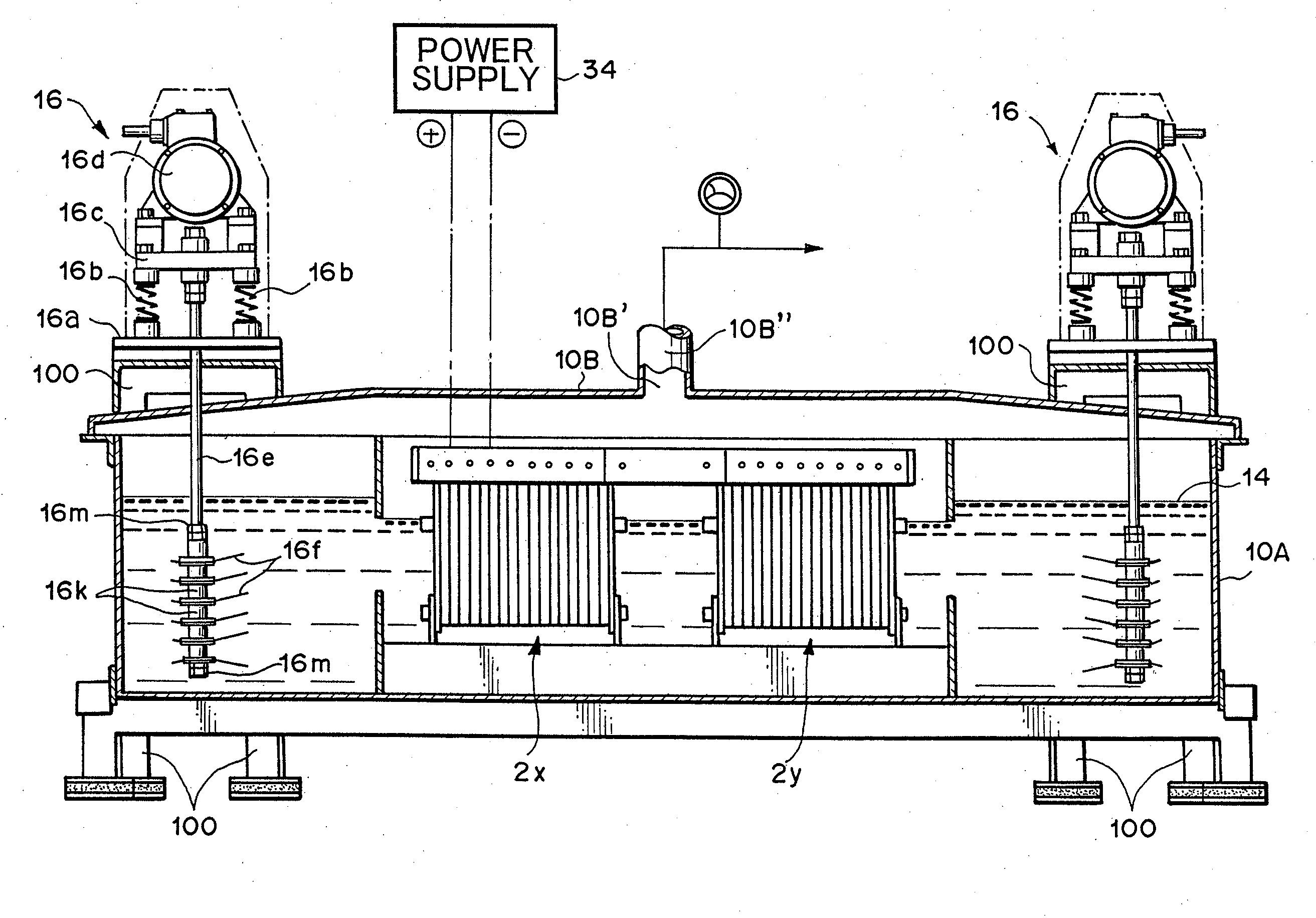
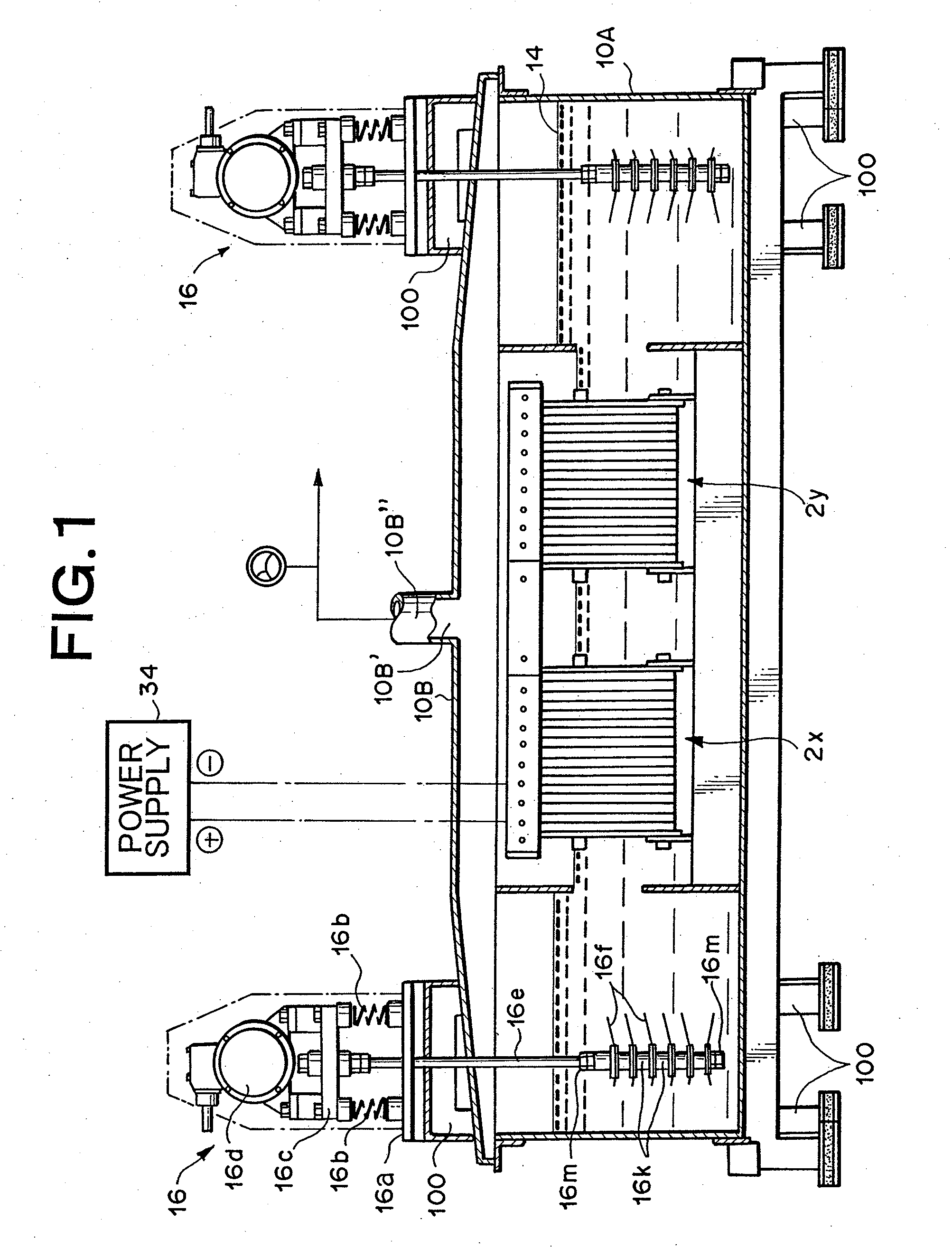
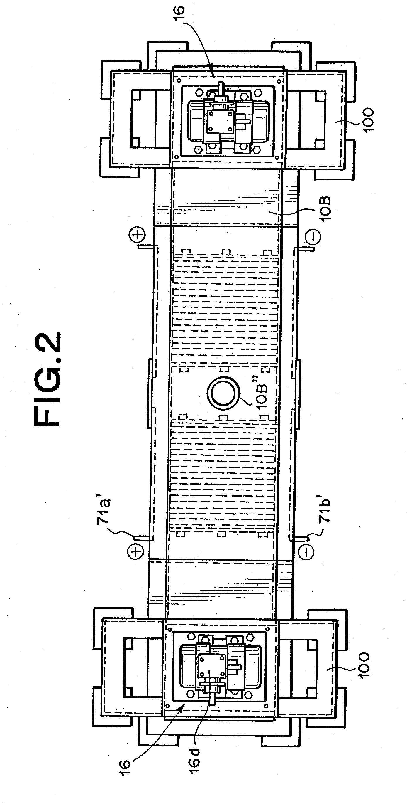
[0097]Utilizing the device as described in FIG. 1 through FIG. 3, but with the lid member 10B described in FIG. 29, hydrogen-oxygen gas was generated and collected under the following conditions.

Electrolytic Cell and Lid Member:

[0098]Manufactured from stainless steel

[0099]270 mm×1660 mm×390 mm (H)

Vibration Generating Means:

[0100]Vibration motor; Uras Vibrator manufactured by Murakami Seild Seisakusho (Corp.) (product name), 250 W×3-phase×200 V, 2-axis type,

[0101]Vibrating blades: Manufactured from stainless steel (SUS304), 6 blades

[0102]Vibrating rod: Manufactured from titanium, 12 mm diameter

[0103]Spacers: 12 pieces, manufactured from titanium

[0104]Clamp members for vibrating blades; 12 pieces

[0105]Packing for vibrating blades: 12 sheets, manufactured by Teflon (registered trademark)

Electrode Group:

[0106]Anodes: 50 sheets, made from platinum plated titanium alloy capable of long-term use without film oxidation

[0107]Cathodes: 50 sheets, made from titanium alloy

[0108]Insulation frame...

second embodiment

[0113]Other than utilizing an AC multiplex current as described in “Electrochemistry” (Society of Japan) Vol. 24, P. 398-403, and pages 449-456 of same volume, the same structure as in the first embodiment was utilized.

[0114]Hydrogen-oxygen gas collection rate was 1,200 liters per hour.

[0115]After continuous operation over a period of one month, stable collection of hydrogen-oxygen gas was achieved at a power consumption lower than the first embodiment.

third embodiment

[0116]Other than using a 270 mm×850 mm×340 mm (H) structure as the electrolytic cell, and using one Hifrerrous KHE-2-2T [100 to 120 Hz] unit manufactured by Murakami Seiki Seisakusho (Corp.) (product name) as the vibration motor, the same structure as in the first embodiment was utilized.

[0117]Hydrogen-oxygen gas collection rate was 800 liters per hour.


PUM

PropertyMeasurementUnit
distanceaaaaaaaaaa
distanceaaaaaaaaaa
vibration frequencyaaaaaaaaaa

Abstract

A hydrogen-oxygen gas generator comprising an electrolytic cell, an electrode group formed from an anode and a cathode mutually installed in that electrolytic cell, a power supply for applying a voltage across the anode and cathode, a gas trapping means for collecting the hydrogen-oxygen gas generated by electrolyzing the electrolyte fluid and a vibration-stirring means. The gas trapping means is comprised of a lid member installed on the electrolytic cell, a hydrogen-gas extraction tube connecting to the hydrogen-oxygen gas extraction outlet of that lid member. A vibration-stirring means for stirring and agitating the electrolytic fluid is supported by support tables. The distance between the adjacent positive electrode and negative electrode within the electrode group is set within a range of 1 to 20 millimeters. The vibration-stirring means is comprised of vibrating motors vibrating at 10 to 200 Hertz, and vibrating blades vibrating within the electrolytic cell and unable to rotate are attached to a vibrating rod linked to the vibrating motors.

Description

[0001]This application is a division of U.S. patent application Ser. No. 10 / 476,195 filed Oct. 28, 2003 entitled “Hydrogen-Oxygen Gas Generator and Method of Generating Hydrogen-Oxygen Gas Using the Generator” which is a 371 of PCT / JP02 / 04400 filed on May 2, 2002, published on Nov. 14, 2002 under publication number WO 02 / 090621 A1 and claims priority benefits of Japanese Patent Application No. 2001-135627 filed May 2, 2001, the disclosures of which are hereby incorporated by reference.BACKGROUND OF THE INVENTION[0002]1. Field of the Invention[0003]The present invention relates to an apparatus and method for generating hydrogen-oxygen gas, and relates in particular to a hydrogen-oxygen gas generator and hydrogen-oxygen gas generating method for highly efficient generation of hydrogen-oxygen gas.[0004]2. Description of Related Art[0005]Electrolysis or electrolytic technology was pioneered by Faraday. The electrolysis of water is known to produce a hydrogen-oxygen gas in a ratio of two...

Claims


Application Information

Patent Timeline
Patent Type & Authority Applications(United States)
IPC IPC(8): C25D17/00C25B1/04C25B1/06C25B9/00C25B15/00
CPCC25B1/04C25B1/06Y02E60/366C25B15/00C25B9/00Y02E60/36C25B11/00C25B1/044C25B9/67C25B15/08
Inventor OMASA, RYUSHIN
Owner OMASA RYUSHIN
Why Eureka
Try Eureka