
Roller table of a rolling train

A technology of roller tables and trains, applied in metal rolling, metal rolling, metal processing equipment, etc., to achieve the effects of improving output, increasing stacking density, and reducing electricity bills

Inactive Publication Date: 2015-04-01
PRIMETALS TECH GERMANY
View PDF4 Cites 0 Cited by
  • Summary
  • Abstract
  • Description
  • Claims
  • Application Information

AI Technical Summary

Problems solved by technology

However, a plurality of roller table sections also means a plurality of converters with the associated acquisition costs associated therewith

Method used


Image

  • Roller table of a rolling train

Examples


Embodiment Construction

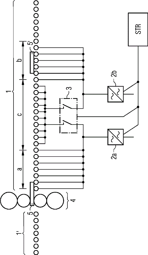
[0016] The illustration includes a rolling stand 4 with roller tables 1, 1' arranged on both sides. The first rolling stock 5 leaves the rolling stand 4 and is transported onward by means of the roller table 1 . On the roller table 1 there is already another rolling stock 5', which has already passed the rolling stand 4 and cooled if necessary.

[0017] For the sake of simplicity, the present invention is only described according to the roller table 1 . Said roller table 1' on the other side of said rolling stand 4 advantageously has the same features.

[0018] The considered roller table 1 has a plurality of rollers. The first roller table section a is fixedly assigned to the first deflector 2 a. The corresponding roller drive is directly connected to the output of the first converter 2a. The second roller table section b is fixedly assigned to the second deflector 2 b. Following the roller table section b, the roller table 1 also has further rollers, the drive supply of...


PUM


Abstract

The invention relates to a roller table (1, 1') for transporting a rolled product (5, 5') in a rolling train, wherein the roller table (1, 1') comprises at least two drive segments operated via converters (2a, 2b). According to the invention, at least one sub-segment (c) of the roller table (1, 1') can be switched by means of a switchover unit (3) on a first converter (2a) and / or on a second converter (2b). According to the invention, the rolling train is made more flexible compared to known solutions while having the same number of converters.

Description

technical field [0001] The invention relates to a roller table for conveying rolling stock in a rolling train, wherein the roller table has at least two drive sections which are run via converters. Furthermore, the invention relates to a method for operating the roller table. Background technique [0002] In a rolling train, the rolled product, for example a metal slab, is transported on roller tables between the individual further processing stations. According to the material, temperature and thickness of the rolled piece, the rolled piece is rolled different times. Here, the individual rolling stands are passed multiple times. The roller tables arranged on both sides of the rolling stand realize the output from the rolling stand, the direction reversal and the conveying to the rolling stand. [0003] Often multiple slabs are rolled per rolling pass in order to achieve a higher throughput. The remaining slabs are temporarily stored temporarily on the roller table secti...

Claims


Application Information

Patent Timeline
Patent Type & Authority Patents(China)
IPC IPC(8): B21B39/12
CPCB21B2201/06B21B39/12
Inventor J.鲁普M.比肖夫B.施密特
Owner PRIMETALS TECH GERMANY
Learn More