
Food mixing machine

A food mixer and mixing bucket technology, which is applied to household appliances, applications, kitchen utensils, etc., can solve the problems of difficulty in stopping the motor, the efficiency of mixing is reduced, and the price is expensive, so as to increase work efficiency, shorten processing time, and increase mixing. The effect of efficiency

Inactive Publication Date: 2013-04-03
DONGGUAN CHAOSHUN MECHANICAL & ELECTRIC INSTALLATION ENG
View PDF5 Cites 7 Cited by
  • Summary
  • Abstract
  • Description
  • Claims
  • Application Information

AI Technical Summary

Problems solved by technology

At present, food mixers at home and abroad are developing rapidly. Most of the existing mixer bodies are made of aluminum alloy, and the transmission mechanism in the body adopts a gear transmission mechanism. The gear transmission mechanism has the advantages of high efficiency, compact structure, reliable operation, and long life. The manufacturing and installation precision is high, the price is expensive, the output torque is small when the ordinary motor is used at low speed, and it is not suitable for occasions where the transmission distance is too large, and the function is relatively single
The control motor transmission is controlled by switches. The motor achieves the highest working efficiency when it is working. It is difficult to stop the motor when the power is disconnected. And it is a waste of time to lift the mixing bucket manually, and the mixing efficiency will be greatly reduced.

Method used


Image

  • Food mixing machine
  • Food mixing machine

Examples


Embodiment Construction

[0017] The present invention will be further described below with reference to the accompanying drawings.

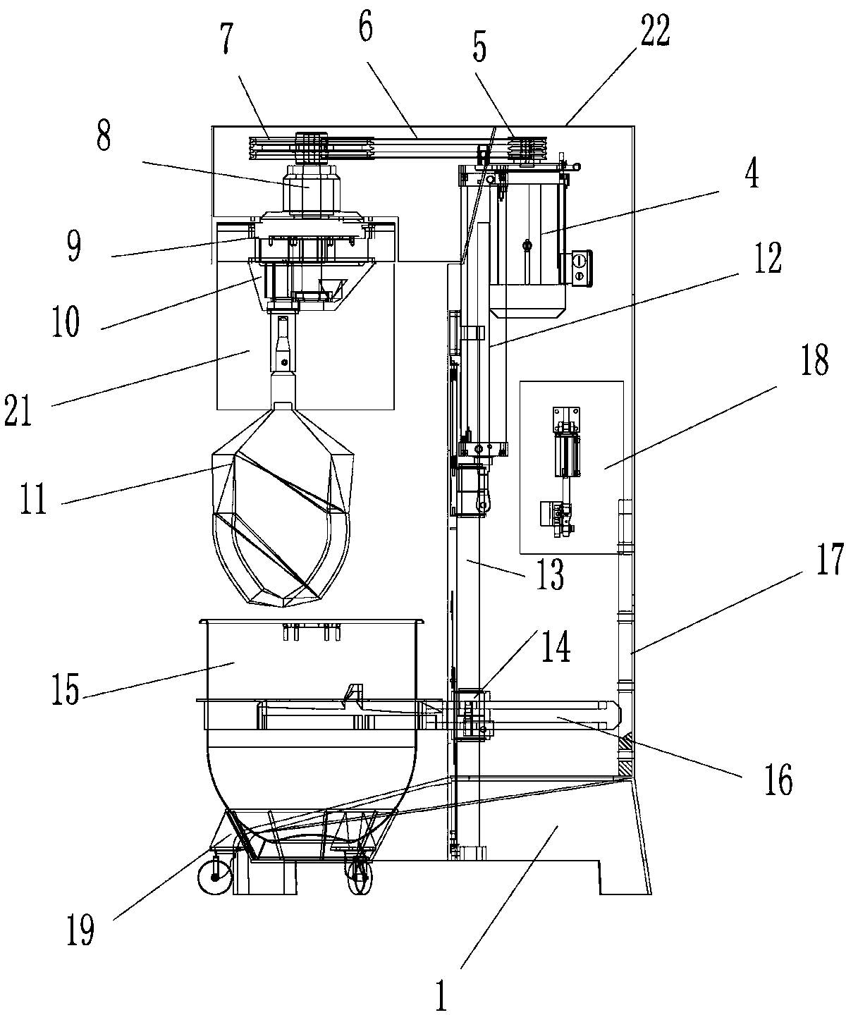
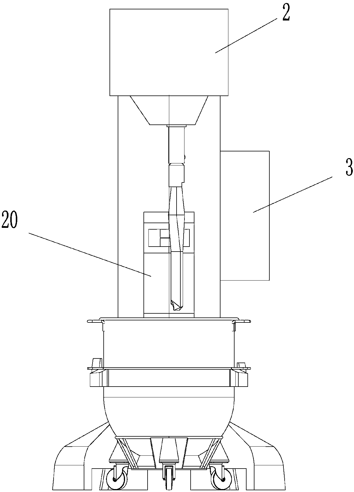
[0018] see figure 1 and figure 2 The shown food mixer includes a base 1, a column 2 is arranged on the base 1, a cantilever 22 is provided on the upper end of the column 2, an electric control box 3 is provided on one side of the column 2, and an electric device is provided inside the cantilever 22. , the electric device includes a reduction motor 4, the motor shaft of the reduction motor 4 is provided with a first pulley 5, the first pulley 5 is connected with the second pulley 7 through a belt 6, the second pulley 7 is fixed on the main shaft 8, and the main shaft 8 is fixed On the planetary turntable mounting plate 9, the lower end of the planetary turntable mounting plate 9 is provided with a planetary turntable 10, and the planetary turntable 10 is provided with a stirring paddle 11; the column 2 is provided with a pneumatic device, and the pneumatic device includ...


PUM


Abstract

The invention discloses a food mixing machine. The food mixing machine comprises a machine base, wherein a column is arranged on the machine base, a suspension arm is arranged on the upper end of the column, one side of the column is provided with an electric cabinet, an electric actuator is arranged in the suspension arm and comprises a gear motor, a first belt pulley is arranged on a motor shaft of the gear motor and is connected with a second belt pulley through a belt, the second belt pulley is fixed on a main shaft, the main shaft is fixed on a mounting plate of a planetary rotary disc, the planetary rotary disc is arranged on the lower end of the mounting plate of the planetary rotary disc, and a mixing blade is arranged on the planetary rotary disc; and a pneumatic actuator is arranged in the column and comprises an air cylinder, one end of the air cylinder is provided with a sliding shaft, a sliding block is sleeved on the sliding shaft, a mixing barrel clamping arm for clamping a mixing barrel is arranged on the sliding block, one end of the mixing barrel clamping arm is connected with a building block which is fixed on the inner wall of the column, and the building block is connected with a clamping arm support seat. The food mixing machine has high cleaning efficiency, mixing tools are convenient to change and clean, and the food mixing machine is simple to operate and is suitable for various food producing industries.

Description

technical field [0001] The invention relates to the technical field of food machinery manufacturing, in particular to a food mixer. Background technique [0002] With the advancement of science and technology and people's higher and higher requirements for the quality of life, the development of food mixing has become increasingly diversified, and the hygiene and performance requirements for food mixers are also getting higher and higher. At present, food mixers at home and abroad are developing rapidly. Most of the existing mixer bodies are made of aluminum alloy, and the transmission mechanism in the body adopts a gear transmission mechanism. The gear transmission mechanism has the advantages of high efficiency, compact structure, reliable operation, and long life. The manufacturing and installation precision is high, the price is expensive, the output torque is small when the ordinary motor is used at low speed, and it is not suitable for occasions where the transmission ...

Claims


Application Information

Patent Timeline
Patent Type & Authority Applications(China)
IPC IPC(8): A47J43/044
Inventor 欧永钊
Owner DONGGUAN CHAOSHUN MECHANICAL & ELECTRIC INSTALLATION ENG
Learn More