High-frequency low-amplitude vibration tooth-extracting instrument

A high-frequency, low-amplitude, vibration generator technology, applied in the direction of dentist forceps, etc., can solve the problems of large damage to surrounding tissues, increase the fear of patients, and difficult to control the use of force, so as to achieve light postoperative complications and reduce fear. , the effect of reducing postoperative pain

Inactive Publication Date: 2013-04-03
温州医科大学附属口腔医院
View PDF5 Cites 7 Cited by
  • Summary
  • Abstract
  • Description
  • Claims
  • Application Information

AI Technical Summary

Problems solved by technology

[0004] Conventional tooth extraction has the following disadvantages: ①The proportion of patients with dental phobia is getting higher and higher, and the main fear objects of alveolar surgery patients include conventional tooth extraction equipment such as tooth elevators and forceps, as well as the conventional clinic environment; It is inevitable to damage periodontal soft and hard tissues, and the degree of damage has great uncertainty. The damage to surrounding tissues is greater than that of forceps, and the damage to periodontal soft and hard tissues will directly affect the healing and restorative treatment after tooth extraction. ; ③In conventional tooth extraction, the operator needs to have a high degree of proficiency in operation, and the operation risk is greater for beginners, and the damage is greater; ④The force of the forceps and tooth lift comes directly from the operator, and the force cannot be quantified and controlled. Poor; ⑤The utilization rate of tooth extraction in tooth extraction is much higher than that of dental forceps, and the operators use various methods of tooth extraction, coupled with poor control of the use of force, tooth extraction and tooth extraction cannot form a mature theoretical system; ⑥Patients with conventional tooth extraction The mouth

Method used


Image

  • High-frequency low-amplitude vibration tooth-extracting instrument
  • High-frequency low-amplitude vibration tooth-extracting instrument

Examples


Embodiment Construction

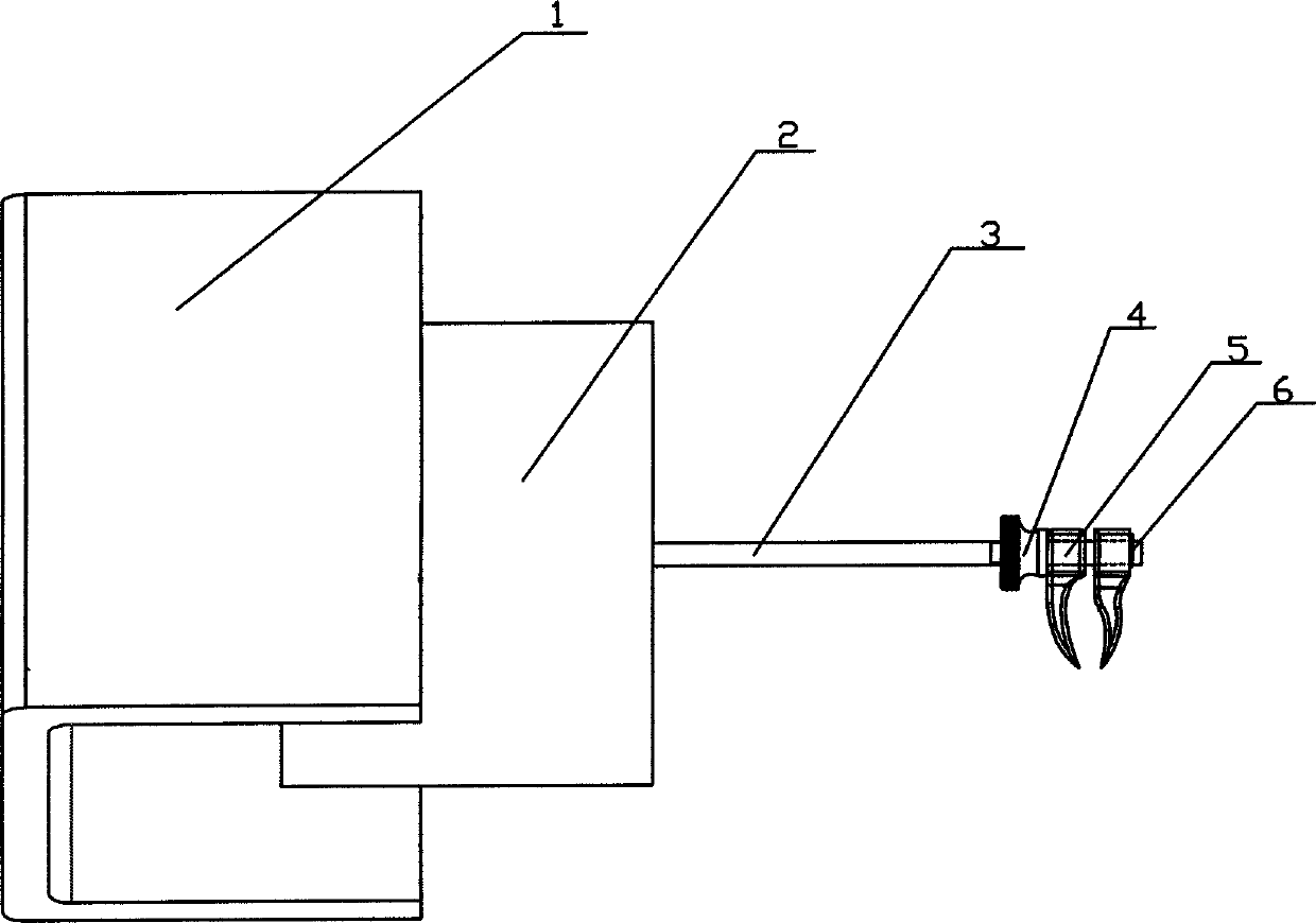
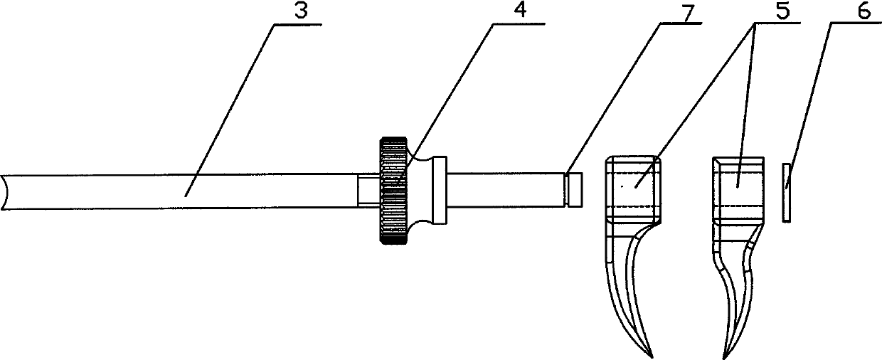
[0017] Such as figure 1 , figure 2 As shown, the present embodiment comprises a high-frequency low-amplitude vibration generator 2, a vibration generator console, a transmission rod 3, a tooth fixing device and a vibrating instrument base 1, and the output end of the vibration generator console is connected to the high-frequency The control end of the low-amplitude vibration generator 2, the output end of the high-frequency low-amplitude vibration generator 2 is connected to one end of the transmission rod 3, the tooth fixing device is located at the other end of the transmission rod 3, and the teeth The body fixing device includes a snap ring 6, a pliers beak 5 matched with the tooth body and a knurled nut 4, the base of the pliers beak 5 is set on the transmission rod 3, and the snap ring 6 is arranged on the pliers beak 5 The outer side of the clamp is stuck on the slot 7 of the transmission rod, and the knurled nut 4 is arranged on the inner side of the pliers beak 5 and...


PUM


Abstract

The invention relates to a tooth-extracting instrument, and in particular relates to a high-frequency low-amplitude vibration tooth-extracting instrument. The high-frequency low-amplitude vibration tooth-extracting instrument comprises a high-frequency low-amplitude vibration generator, a transmission rod and a tooth fixing device, wherein the output end of the high-frequency low-amplitude vibration generator is connected to one end of the transmission rod; the tooth fixing device is arranged at the other end of the transmission rod; the tooth fixing device comprises a clamping ring, a beak matched with a tooth and a knurled nut; the basal part of the beak is sleeved on the transmission rod; the clamping ring is arranged outside the beak and clamped on a clamping groove of the transmission rod; and the knurled nut is arranged inside the beak and spirally connected with the transmission rod. The invention aims to design the high-frequency low-amplitude vibration tooth-extracting instrument, which has the advantages of being controllable in acting force, adjustable, strong in operability and predictable in tooth-extracting effect. Compared with the prior art, the high-frequency low-amplitude vibration tooth-extracting instrument disclosed by the invention has the advantages of being easy to operate, convenient for teaching and small in operative wound and is capable of relieving dread feeling of dental patients and the like.

Description

technical field [0001] The invention relates to a tooth extraction instrument, in particular to a tooth extraction instrument with high-frequency and low-amplitude vibration. Background technique [0002] Tooth extraction is a very common procedure in oral and maxillofacial surgery. Tooth extraction indications include: ① various dental diseases that cannot be cured and preserved; ② people with symptoms of various misplaced teeth, impacted teeth and embedded teeth; ③ pathogenic teeth or lesion teeth that cause other diseases; ④ aesthetic requirements or orthodontic needs Extracted tooth. [0003] The current clinical routine tooth extraction mainly includes: ① using forceps to clamp the crown and then loosen the tooth in the buccal-lingual direction (lip-lingual, buccal-palatine direction) and then forceps out; Push out your teeth. These operations have relatively low equipment requirements and are easy to popularize in primary hospitals, but the success of the operation ...

Claims


Application Information

Patent Timeline
IPC IPC(8): A61C3/14
Inventor 胡荣党孙仁义朱丹峰沈佳威付敏刘欢欢
Owner 温州医科大学附属口腔医院
Why Eureka
Try Eureka