Knee-joint hinge of standing period control orthosis
A knee joint and orthosis technology, applied in the field of orthosis knee joint hinges and new stance control orthosis knee joint hinge fields, can solve the problems of increased cardiopulmonary load, high price, technical confidentiality, etc., and achieves ease of walking and guaranteed stability sexual effect
- Summary
- Abstract
- Description
- Claims
- Application Information
AI Technical Summary
Problems solved by technology
Method used
Image
Examples
Embodiment 1
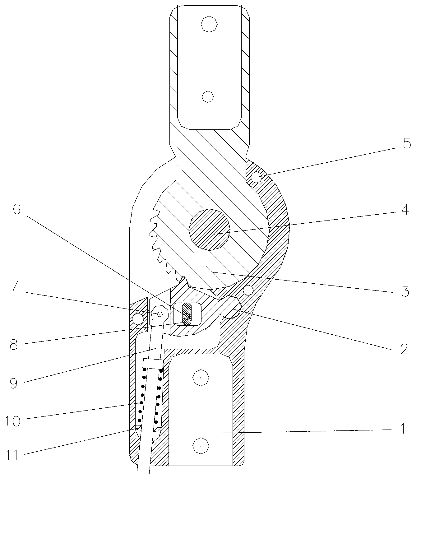
[0049] Embodiment 1, knee joint hinge
[0050] The knee joint hinge of the present invention comprises the following components:
[0051] Lower hinge body 1, claw 2, tooth hinge body 3, fixed shaft 4, rivet pin 5, lock shaft 6, pull rod shaft 7, lock pin 8, pull rod 9, spring 10, retaining ring 11.
[0052] In the knee joint hinge, the connection relationship of each component is as follows:
[0053] The toothed hinge body 3 passes through the fixed shaft 4 and is installed on the knee joint hinge. The claw 2 is arranged under the toothed hinge body 3. One end of the pull rod 9 passes through the pull rod shaft 7 and is installed on the claw 2. The other end of the pull rod 9 is connected to the pull wire 16. A lock pin 8 with a lock shaft 6 is provided in the middle of the claw 2. By turning the lock pin 8, the claw 2 can realize three different functions, that is, full lock, no lock, and knee-ankle linkage unlocking.
[0054] Wherein, a spring 10 and a retaining ring 11 ar...
Embodiment 2
[0055] Embodiment 2, the orthosis of knee joint hinge of the present invention
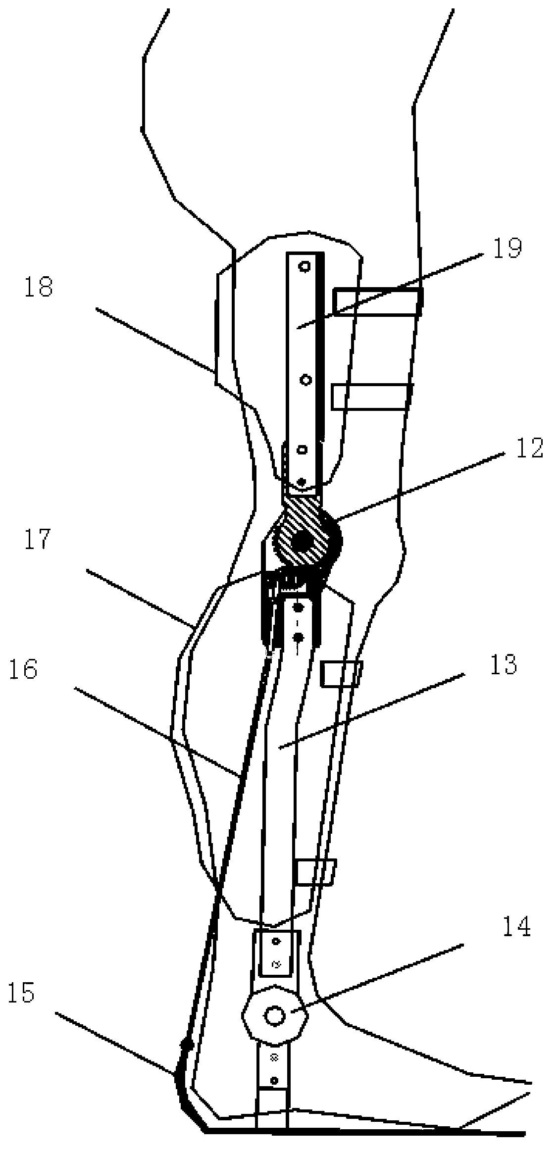
[0056] The orthosis of the present invention comprises the following parts: knee joint hinge 12, calf brace 13, ankle hinge 14, pedal 15, backguy 16, calf hoop 17, thigh hoop 18 and thigh brace 19;
[0057] The connection relation of described each parts is as follows: thigh support bar 19 and calf support bar 13 are respectively fixedly installed on thigh hoop 18 and calf hoop 17, and thigh support bar 19 and calf support bar 13 are connected together by knee joint hinge 12, and calf The lower end of support bar 13 connects pedal 15, and the heel portion of pedal 15 is provided with a backguy 16, and the top of backguy 16 connects the pull bar 9 on the knee joint hinge 12, and ankle joint hinge 14 is housed on the calf support bar 13.
Embodiment 3
[0058] Embodiment 3, the using method of orthosis of the present invention
[0059] Combine now figure 1 and figure 2 Illustrate the use method of the present invention:
[0060] Knee-ankle linkage unlocking mode (turn lock pin 8 to adjust to knee-ankle linkage unlocking mode)
[0061] 1. Adjust the tightness of the cable through the swing distance of the lower limb on the side of the orthosis to control the unlocking angle of the knee joint;
[0062] 2. The patient wears the lower limb orthosis;
[0063] 3. After the patient steps out of the contralateral leg (the leg not wearing the orthosis), the center of gravity gradually shifts to the orthosis side leg (the leg wearing the orthosis) during the support period of the lower limb on the orthosis side;
[0064] 4. Through the forward transfer of the center of gravity on the side of the orthosis, when the center of gravity is transferred to the front of the sole of the foot, the ankle joint is dorsiflexed, triggering the ...
PUM
 Abstract
Description
Claims
Application Information
 - R&D
- Intellectual Property
- Life Sciences
- Materials
- Tech Scout
- Unparalleled Data Quality
- Higher Quality Content
- 60% Fewer Hallucinations
Browse by: Latest US Patents, China's latest patents, Technical Efficacy Thesaurus, Application Domain, Technology Topic, Popular Technical Reports.
© 2025 PatSnap. All rights reserved.Legal|Privacy policy|Modern Slavery Act Transparency Statement|Sitemap|About US| Contact US: help@patsnap.com


