Bearing cleaning machine

A technology for cleaning bearings and bearings, applied in cleaning methods and appliances, cleaning methods using liquids, chemical instruments and methods, etc., can solve problems such as harsh working environments and large oil pollution, and achieve good cleaning effects

Inactive Publication Date: 2013-04-03
CIXI HAIKE MACHINERY EQUIP TECH
View PDF11 Cites 15 Cited by
  • Summary
  • Abstract
  • Description
  • Claims
  • Application Information

AI Technical Summary

Problems solved by technology

[0006] The disadvantages of the existing bearing cleaning machines are: the oil washing tank is used for oil washin

Method used


Image

  • Bearing cleaning machine
  • Bearing cleaning machine
  • Bearing cleaning machine

Examples


Embodiment Construction

[0029] The present invention will be described in further detail below in conjunction with the accompanying drawings and specific embodiments.

[0030] refer to figure 1 , figure 2 , image 3 , Figure 4 , a bearing cleaning machine, comprising a frame, the frame has a working platform 1, the front end of the working platform 1 is provided with four feeding vibrating plates 2 for arranging the bearings into a flat queue, and the working platform The front end of 1 is also provided with four horizontal feed rails 3, the input end of the feed rail 3 is connected with the output end of the feeding vibrating plate 2;

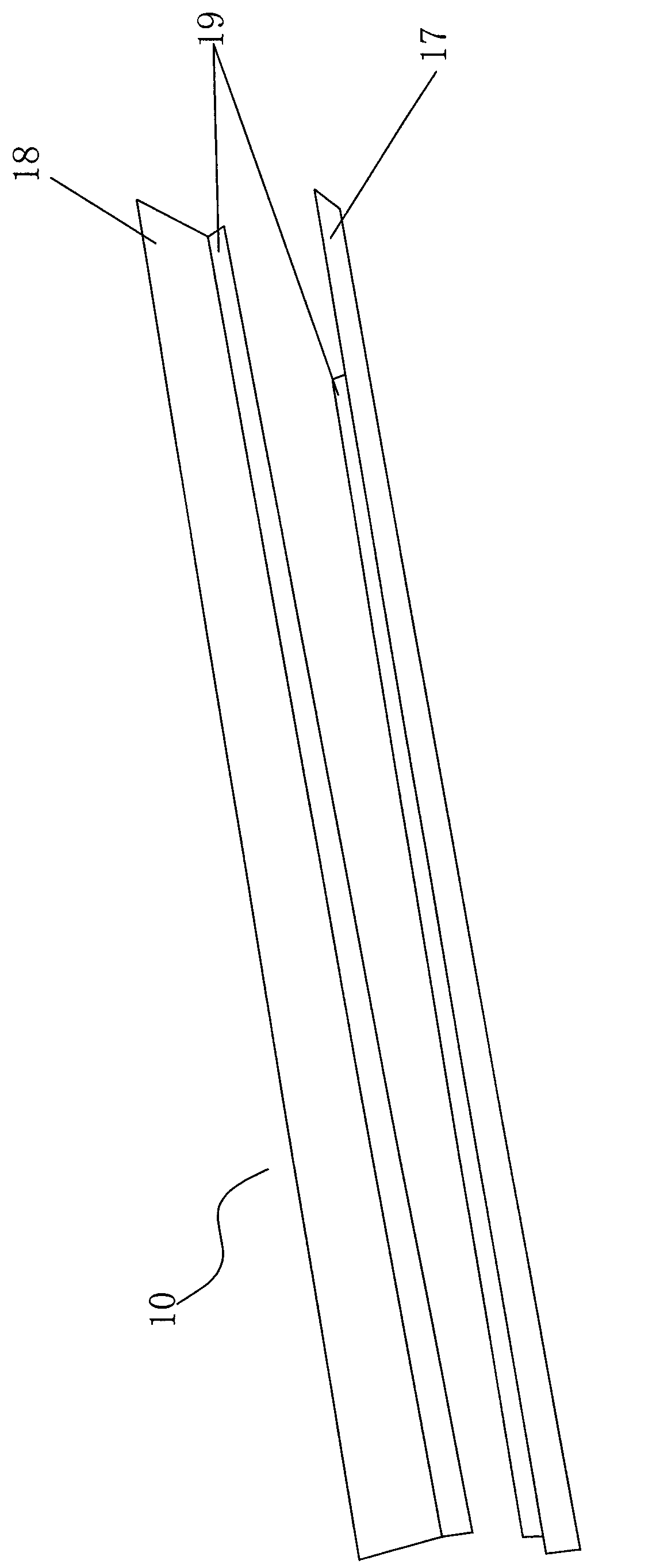
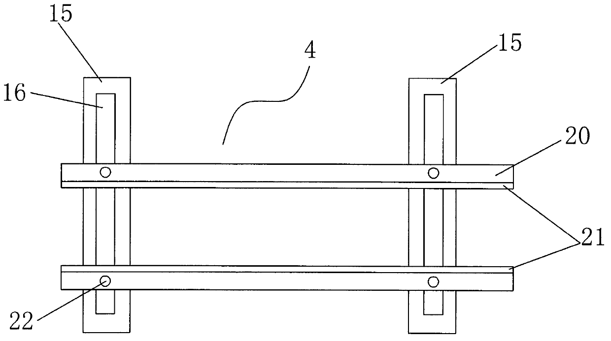
[0031] The working platform 1 is also provided with four front feed rails 4 on which four longitudinal bearings can lie horizontally, the input end of the front feed rail 4 is connected with the output end of the feed rail 3, and the front feed rail 4 is connected with the output end of the feed rail 3. The top of the input end of the feeding track 4 is provide...


PUM


Abstract

The invention discloses a bearing cleaning machine, comprising a stand, wherein the stand is provided with a work platform, and the front end of the work platform is provided with a feeding vibration disk and is further provided with a transverse feeding rail; the work platform is provided with a front longitudinal feeding rail and is provided with a first water washing box, a first ultrasonic cleaning box, a second water washing box and a first blow-drying box in sequence from front to back, and the front feeding rail penetrates through the first water washing box, the first ultrasonic cleaning box, the second water washing box and the first blow-drying box in sequence; the work platform behind the first blow-drying box is provided with an overturn rail for turning a bearing for 180 degrees, and the inner side of the overturn rail is provided with a back longitudinal feeding rail; and the work platform behind the overturn rail is provided with a second ultrasonic cleaning box, a second blow-drying box, a third blow-drying box and a baking box in sequence from front to back. According to the invention, the water washing boxes and the ultrasonic cleaning boxes are arranged to clean the bearing, so that the cleaning effect is good, and environment pollution cannot be caused due to adoption of water for washing.

Description

(1) Technical field [0001] The invention relates to a bearing cleaning machine. (2) Background technology [0002] The general structure of the existing bearing cleaning machine is as follows: including a frame, the frame has a working platform, the front end of the working platform is provided with a feeding vibrating plate for arranging the bearings into a flat queue, and the front end of the working platform is also provided with a horizontal feeder. Material track, the input end of the feeding track is connected with the output end of the feeding vibrating plate; [0003] The working platform is also equipped with a longitudinal bearing on which the feeding track can lie horizontally. The input end of the feeding track is connected with the output end of the feeding track. A front sensor is arranged above the input end of the feeding track. A feeding cylinder is provided, and the feeding cylinder is connected to the sensor signal; [0004] There are also several oil wa...

Claims


Application Information

Patent Timeline
IPC IPC(8): B08B3/12B08B3/02
Inventor 蒋高义
Owner CIXI HAIKE MACHINERY EQUIP TECH
Why Eureka
Try Eureka