Liftable working table

A technology for raising and lowering workbenches and lifting pipes, which is applied to workbenches, manufacturing tools, etc., can solve the problems of time-consuming and laborious, inconvenient use, cumbersome lifting and lowering operations, etc., and achieve the effects of compact overall structure, convenient storage and transportation, and high safety performance.

Inactive Publication Date: 2013-04-03
谢翠斌
View PDF8 Cites 31 Cited by
  • Summary
  • Abstract
  • Description
  • Claims
  • Application Information

AI Technical Summary

Problems solved by technology

[0002] In mechanical maintenance, especially when repairing cars, the height of the workbench where tools are placed needs to be adjusted at any time to meet the maintenance needs. The traditional lifting workbench can only be manually adjusted to the appropriate height under no-load conditions, which is inconvenient to use.
The existing lifting workbench is divided into manual lifting and automatic lifting. The applicant’s patent No. CN200820237923.9 discloses the lifting workbench. Through the groove on the column and the stop nut of the lifting tube, the work plate can be lifted and lowered with the lifting tube. At the same time, lock the stop nut to control the fixed height of the work plate. The disadvantage is that the tool plate must be manually raised and lowered to lock the stop nut after the tool plate is lowered. .9 In the disclosed pneumatic lifting workbench, the lifting of the tool tray is realized by the lifting of the air pump to drive the tool tray. If the air pump fails, the workbench cannot be lifted and lowered, the use and safety performance is low, the replacement and maintenance are troublesome, and the cost is high

Method used


Image

  • Liftable working table

Examples


Embodiment Construction

[0010] The present invention will be further described below in conjunction with drawings and embodiments.

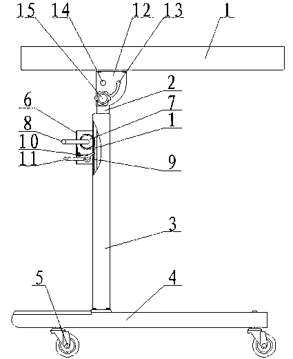
[0011] figure 1 As shown, the lifting workbench mainly includes a tool tray 1, a lifting pipe 2, a column 3, an underframe 4, a hinge seat 12 and a lifting device 6. The lower end of the tool tray 1 is fixedly connected to the hinge base 12, and the upper part of the lifting tube 2 is hinged on the hinge point 14 of the hinge base 12. The hinge base 12 is provided with an arc track groove 13, and the lifting tube 2 is provided with a locking screw 15, which is locked. The bolt part of the screw 15 is placed in the arc track groove 13 of the hinge seat 12 and can slide in the arc track groove 13, and the nut part of the locking screw 15 presses the hinge seat 12 and the lifting tube 2, and the lifting tube 2 can Rotate around the hinge point 14 along the direction of the arc track groove 12, the lifting tube 2 is set in the column 3, the column 3 is vertically connected...


PUM


Abstract

The invention relates to a liftable working table which comprises a tool plate, an underframe, a lifting pipe and an upright post, wherein the lower end surface of the tool plate is connected with the lifting pipe sleeved in the upright post; the upright post is perpendicularly connected with the underframe; universal wheels are arranged at the lower end of the underframe; a rack is arranged on the side wall of the lifting pipe; a lifting device is arranged on the upright post and is provided with a gear and a pawl therein; the gear and the pawl are mutually meshed; a rotary handle is arranged on the gear; a retaining operating rod is arranged at the tail end of the pawl; and the head of the pawl is clamped into the mouth of the rack. According to the invention, the gear of the lifting device is meshed with the rack of the lifting pipe so as to lift the tool plate, and besides, the lower end of the tool plate is connected with a hinged support so as to realize movable folding of the tooling plate. The liftable working table has the advantages of compact integral structure, convenience in lifting and folding, high safety performance, low failure rate, long service life and convenience in storage and transportation.

Description

technical field [0001] The invention relates to an elevating workbench, in particular to a foldable and manual elevating workbench. Background technique [0002] In mechanical maintenance, especially when repairing cars, the height of the workbench where tools are placed needs to be adjusted at any time to meet the maintenance needs. The traditional lifting workbench can only be manually adjusted to the appropriate height under no-load conditions, which is inconvenient to use. . The existing lifting workbench is divided into manual lifting and automatic lifting. The applicant’s patent No. CN200820237923.9 discloses the lifting workbench. Through the groove on the column and the stop nut of the lifting tube, the working plate can be lifted and lowered with the lifting tube. At the same time, lock the stop nut to control the fixed height of the work plate. The disadvantage is that the tool plate must be manually raised and lowered to lock the stop nut after the tool plate...

Claims


Application Information

Patent Timeline
IPC IPC(8): B25H1/04B25H1/16
Inventor 谢翠斌
Owner 谢翠斌
Why Eureka
Try Eureka