Controllable stacking robot

A palletizing robot and rack technology, applied in the field of industrial robots, can solve the problems of joint error accumulation, heavy arm, large inertia, etc., achieve small motion inertia, flexible trajectory, and meet the effect of high-speed handling and palletizing

Inactive Publication Date: 2013-04-03
GUANGXI UNIV
View PDF7 Cites 38 Cited by
  • Summary
  • Abstract
  • Description
  • Claims
  • Application Information

AI Technical Summary

Problems solved by technology

[0003] The object of the present invention is to provide a controllable palletizing robot, all driving motors are installed on the frame, which can solve the problem of heavy arms, poor rigidity, Due to problems such as large inertia and accumulation of joint errors, the robot has better dynamic performance and can better meet the requirements of high-speed heavy-duty handling and palletizing

Method used


Image

  • Controllable stacking robot
  • Controllable stacking robot
  • Controllable stacking robot

Examples


Embodiment Construction

[0023] The technical solutions of the present invention will be further described below in conjunction with the accompanying drawings and embodiments.

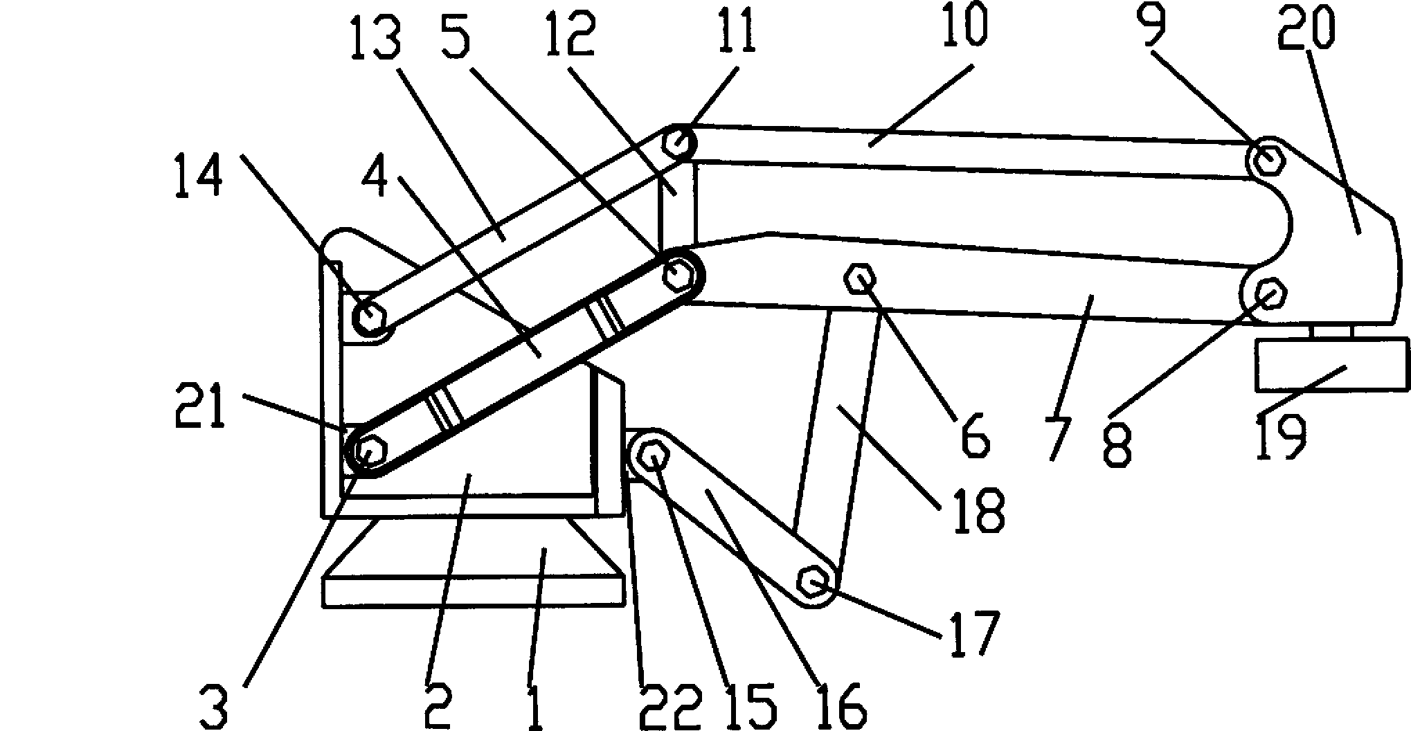
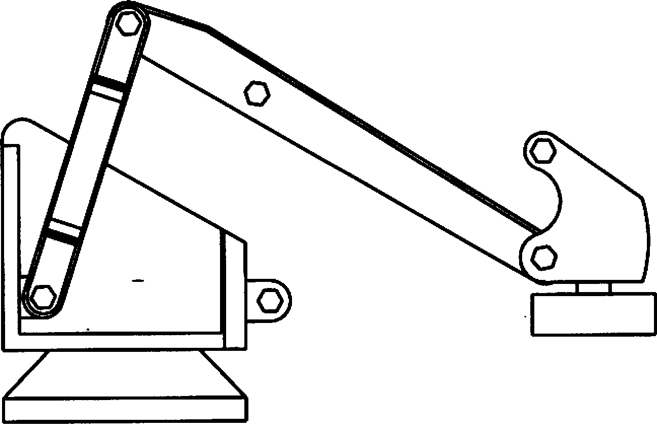
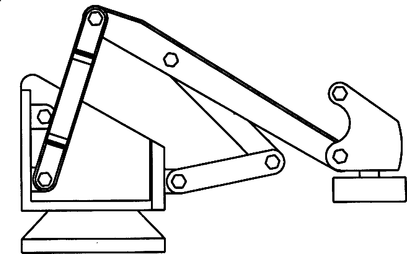
[0024] control figure 1 , 6 , 7, 8 and 9, a controllable palletizing robot, including a large arm swing branch chain, a small arm swing branch chain, an attitude maintaining branch chain, an end effector and a frame. The frame is installed on the rotary platform to realize the handling and palletizing work in the entire robot space.

[0025] control figure 1 , 2 , the boom swing branch chain is connected by the boom 4, the small arm 7, the end effector 20 and the frame 2, one end of the boom 4 is connected to the frame 2 through the first rotating pair 3, and the other end is connected to the frame 2 through the first rotating pair The second swivel pair 5 is connected to the small arm 7, one end of the small arm 7 is connected to the boom 4 through the second swivel pair 5, and the other end is connected to the end effect...


PUM


Abstract

The invention relates to a controllable stacking robot, which comprises a large arm swinging branched chain, a small arm swinging branched chain, a gesture maintaining branched chain, a tail end actuator and a machine frame. The robot completes the tasks of transporting and stacking on a space as well as flexible and changeable trajectory output according to the combined movement of the large arm swinging branched chain and the small arm swinging branched arm. During a working process, according to two groups of parallelogram structures of the gesture maintaining branched chain, the tail end actuator can be guaranteed to maintain in a horizontal state all the time, all servo motors are arranged on the machine frame, rod pieces can be made into light rods, the robot has small movement inertia and excellent dynamic performance, and can be better satisfied with the requirement of transporting stacks at a high speed. According to the controllable stacking robot, by the adoption of a novel connecting rod mechanism, as a connecting transmission mechanism is simple in structure, the stress of each rod is improved, and the robot is more suitable for manufacturing a large-scale stacking machine.

Description

technical field [0001] The invention relates to the field of industrial robots, in particular to a controllable palletizing robot. Background technique [0002] Palletizing robots are widely used in automatic handling operations such as machine tool loading and unloading, stamping machine automated production lines, automatic assembly lines, palletizing, and containers. Existing palletizing robots mainly have three structural types: Cartesian coordinate type, cylindrical coordinate type and joint type. Among them, the articulated palletizing robot has gradually become the most important structural form of the palletizing robot because of its compact structure, flexible movement, small footprint, and large working space. However, the drive motors of such traditional palletizing robots with an open-chain series structure need to be installed at the joints, resulting in problems such as heavy weight, poor rigidity, large inertia, and accumulation of joint errors. The dynamic p...

Claims


Application Information

Patent Timeline
Patent Type & Authority Applications(China)
IPC IPC(8): B25J9/06B25J9/10B65G61/00
Inventor 蔡敢为张金玲潘宇晨高德中王小纯
Owner GUANGXI UNIV
Why Eureka
Try Eureka