Thirteen-rod controllable stacking mechanism

A stacking and connecting rod technology, applied in the field of thirteen-bar controllable stacking mechanism, can solve the problems of joint error accumulation, heavy arm, poor rigidity, etc., to achieve stable work, flexible trajectory, and strong flexible output. Effect

Inactive Publication Date: 2015-05-20
GUANGXI UNIV
View PDF6 Cites 1 Cited by
  • Summary
  • Abstract
  • Description
  • Claims
  • Application Information

AI Technical Summary

Problems solved by technology

[0004] The purpose of the present invention is to provide a thirteen-bar controllable palletizing mechanism, all driving motors are installed on the frame, which can solve the problem that the motors of traditional open-chain series robots are installed at the hinges, resulting in heavy arms, poor rigidity, and low inertia. The robot has better dynamic performance and can better meet the requirements of high-speed heavy-duty handling and palletizing.

Method used


Image

  • Thirteen-rod controllable stacking mechanism
  • Thirteen-rod controllable stacking mechanism
  • Thirteen-rod controllable stacking mechanism

Examples


Embodiment Construction

[0022] The technical solutions of the present invention will be further described below through the accompanying drawings and embodiments.

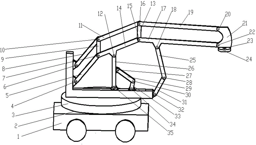
[0023] A thirteen-rod controllable palletizing mechanism, including a rotating frame 3, a mobile platform 1, a large arm 5, a middle arm 14, a small arm 17, an end effector 21, a fourth connecting rod 8, a fifth connecting rod 11, The sixth connecting rod 19, the first supporting rod 9, the second supporting rod 13, the second connecting rod 26, the second active rod 33, the first connecting rod 29, the third active rod 31, the third connecting rod 25 and the flange disk 24;

[0024] The rotating frame 3 is connected to the mobile platform 1 through the first rotating pair 2;

[0025] One end of the boom 5 is connected to the rotating frame 3 through the first swivel pair 4, the other end of the boom 5 is connected to one end of the middle arm 14 through the second compound hinge 7, and the other end of the middle arm 14 is connected to ...


PUM


Abstract

Provided is a thirteen-rod controllable stacking mechanism. One end of a large arm of the stacking mechanism is connected to the other end of a rotating machine frame and is connected with one end of a middle arm. The other end of the middle arm is connected with one end of a small arm. The other end of the small arm is connected with a tail end executing device. One end of a fourth connecting rod is connected to a rotating machine frame. The other end of the fourth connecting rod is connected with one end of a fifth connecting rod. The other end of the fifth connecting rod is connected with one end of a sixth connecting rod. The other end of the sixth connecting rod is connected with the tail end executing device. One end of the first supporting rod is connected to a second composite hinge. The other end of the first supporting rod is connected with a first composite hinge. One end of a second supporting rod is connected to a fourth composite hinge. The other end of the second supporting rod is connected to a third composite hinge. One end of a second connecting rod is connected to the rotating machine frame, and the other end of the second connecting rod is connected to the middle arm. One end of a second driving rod is connected to the rotating machine frame, and the other end of the second driving rod is connected with one end of a first connecting rod. The other end of the first connecting rod is connected to the second connecting rod. Three equal quadrangle structures are used for enabling the tail end executing device to be kept horizontal all the time, and bearing capacity is high.

Description

technical field [0001] The invention relates to the field of industrial robots, in particular to a thirteen-rod controllable palletizing mechanism. Background technique [0002] Palletizing robots are widely used in automatic handling operations such as machine tool loading and unloading, stamping machine automated production lines, automatic assembly lines, palletizing, and containers. Existing palletizing robots mainly have three structural types: Cartesian coordinate type, cylindrical coordinate type and joint type. Among them, the articulated palletizing robot has gradually become the main structural form of the palletizing robot because of its compact structure, flexible movement, small footprint, and large working space. However, the drive motors of this type of palletizing robot with traditional open-chain series structure must be installed at the joints, resulting in problems such as heavy weight, poor rigidity, large inertia, and accumulated joint errors. The dynam...

Claims


Application Information

Patent Timeline
IPC IPC(8): B65G61/00
CPCB65G61/00
Inventor 蔡敢为王龙张林关卓怀张永文朱凯君李智杰王麾石慧范雨黄院星王少龙
Owner GUANGXI UNIV
Why Eureka
Try Eureka