Built-in air suction cylinder

A cylinder and cylinder body technology, applied in the field of built-in suction cylinder, can solve the problems of fatigue of the joint between the leather tube and the cylinder, affecting the life of the adsorption mechanism of the manipulator, and the space occupied by the external suction cup assembly, etc.

Inactive Publication Date: 2013-04-03
WENZHOU ZHONGKE AUTOMATION EQUIP
View PDF4 Cites 2 Cited by
  • Summary
  • Abstract
  • Description
  • Claims
  • Application Information

AI Technical Summary

Problems solved by technology

Since the suction cup assembly must be installed at the lower end of the cylinder, the external suction cup assembly occupies a certain space
In addition, since the cylinder moves with the leather tube and the air pipe joint to follow the expansion and contraction movement, the leather tube and the cylinder joint are fatigued under high-frequency movement, which affects the life of the manipulator adsorption mechanism.

Method used


Image

  • Built-in air suction cylinder
  • Built-in air suction cylinder
  • Built-in air suction cylinder

Examples


Embodiment Construction

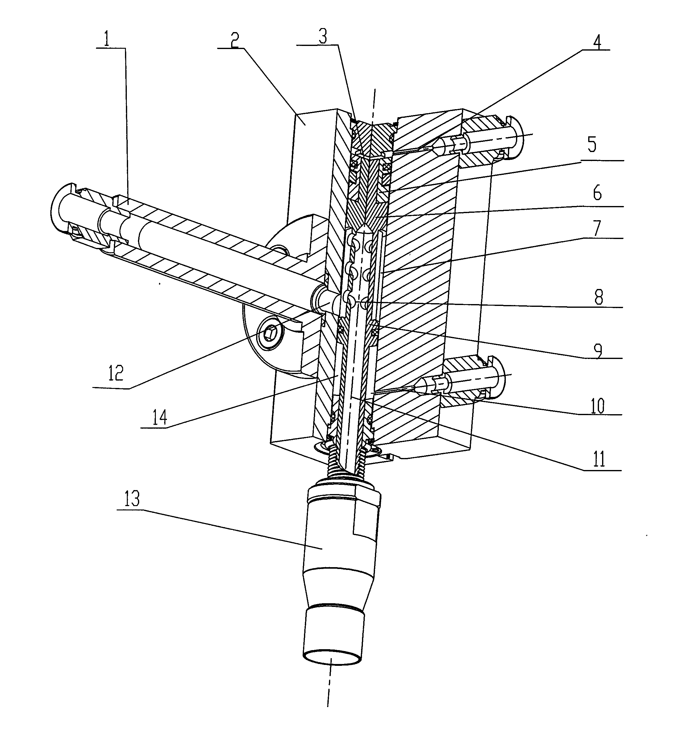
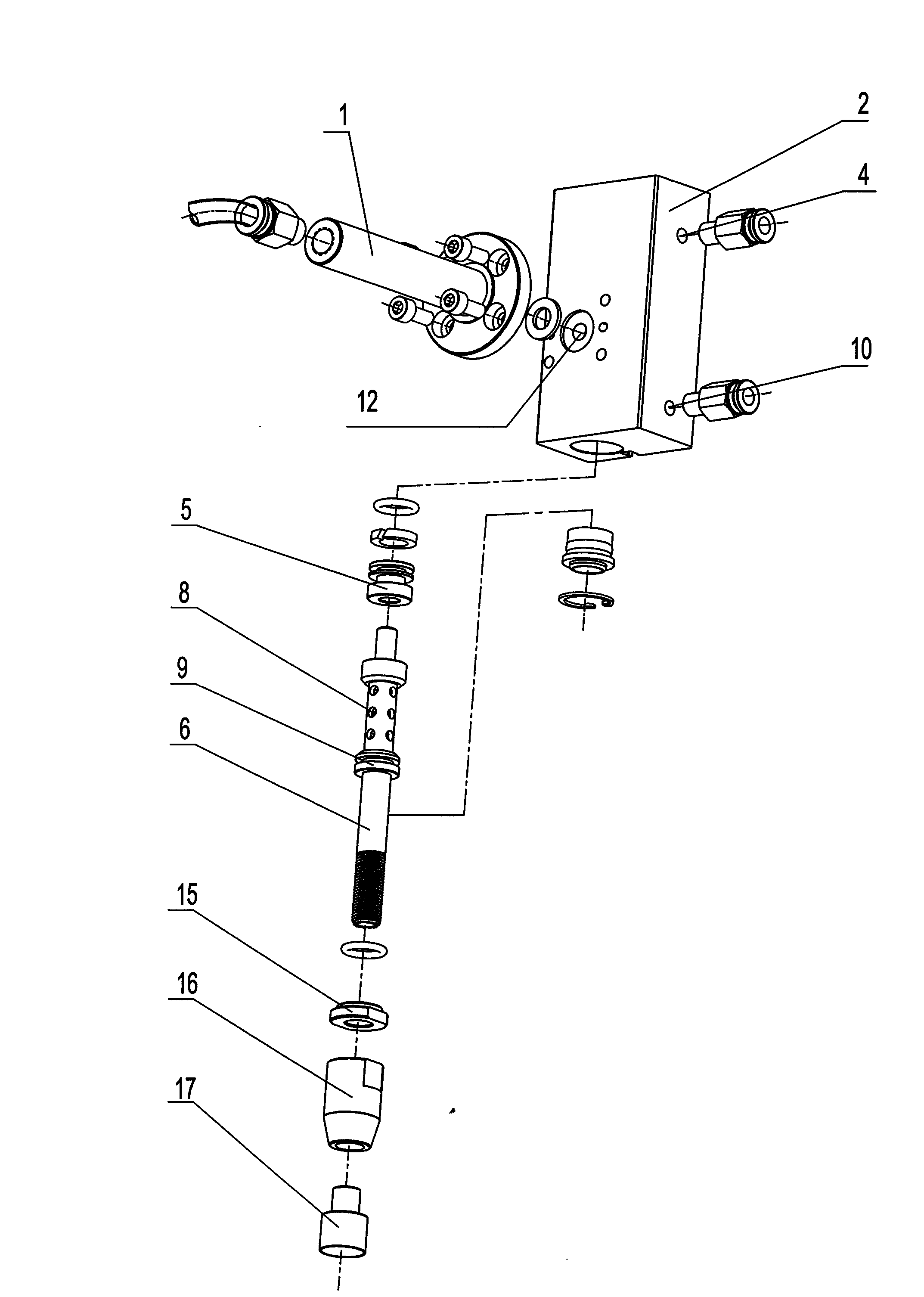
[0012] Such as figure 1 , figure 2 As shown, the present embodiment comprises cylinder body 2, piston rod 6, piston, and described piston is made up of upper and lower piston 5,9, and described upper piston 5 and described lower piston 9 are arranged on described piston rod with a certain distance apart. 6, the upper piston 5 and the upper end of the cylinder chamber in the cylinder body form an upper piston chamber 3, and the lower piston 9 and the lower end of the cylinder chamber in the cylinder body form a lower piston chamber 14, and the upper, The cylinder block corresponding to the lower piston cavity 3, 14 is respectively provided with an air intake passage 4, 10, and the cylinder cavity formed between the upper piston 5 and the lower piston 9 and the piston rod form an air intake chamber 7, which is connected to the intake air channel 7. The corresponding cylinder body of the air chamber 7 is provided with an air chamber outlet hole 12, and the piston rod 6 is provi...


PUM


Abstract

The invention relates to a cylinder, in particular to a built-in air suction cylinder with an air suction function. The built-in air suction cylinder comprises a cylinder body, a piston rod and a piston. The piston consists of an upper piston and a lower piston. The upper piston and the lower piston are arranged on the piston rod at a certain distance to enable the chamber of the cylinder to form two piston chambers. The middle section of the chamber of the cylinder forms an air inlet chamber. An air chamber air outlet is arranged in the cylinder body corresponding to the air inlet chamber. An axial air flow passage is arranged in the piston rod. A radial air outlet is arranged in the body of the piston rod at a position where the air inlet chamber is arranged. The radial air outlet is connected with the outlet end of the axial air flow passage. The inlet end of the axial air flow passage stretches out of the external end of the piston rod. The invention aims at designing the built-in air suction cylinder with the air suction function, a small size and a small structure. Compared with the prior art, the built-in air suction cylinder provided by the invention has the advantages that the cylinder has dual functions of a manipulator and an adsorption mechanism, the production cost is low, the workpiece adsorption accuracy is high, the working response time is short, convenience is provided for the reasonable layout of automatic corollary equipment and the space is saved.

Description

technical field [0001] The invention relates to an air cylinder used on automatic mechanical equipment, in particular to a built-in air suction cylinder with air suction function. Background technique [0002] At present, automatic equipment at home and abroad generally use manipulators and suction cups to grab small workpieces after they are transported in place. The traditional manipulator adopts cylinder movement and external suction cup assembly. The air pressure sucks the workpiece through the air pipe, air pipe joint and suction cup, and the working process is completed by the telescopic movement of the cylinder. Because the suction cup assembly must be installed at the lower end of the cylinder, the external suction cup assembly occupies a certain space. In addition, because the movement of the cylinder simultaneously brings the leather tube and the air pipe joint to follow the expansion and contraction movement, the leather tube and the air cylinder joint are fatig...

Claims


Application Information

Patent Timeline
Patent Type & Authority Applications(China)
IPC IPC(8): B25J15/06
Inventor 吴圣明庄瑞国
Owner WENZHOU ZHONGKE AUTOMATION EQUIP
Why Eureka
Try Eureka