Membrane positioning structure, backlight module and display device

A technology for positioning structures and membranes, applied in lighting and heating equipment, optics, electric light sources, etc., can solve the problem of taking up a lot of space, and achieve the effect of small space occupation, simplified design, and promotion of narrow edge development.

Active Publication Date: 2013-04-03
HISENSE VISUAL TECH CO LTD
View PDF6 Cites 12 Cited by
  • Summary
  • Abstract
  • Description
  • Claims
  • Application Information

AI Technical Summary

Problems solved by technology

[0005] The embodiment of the present invention provides a diaphragm positioning structure to solve the technical problem in the prior art that the diaphragm relies on rivet posts to locate and occupy a lot of space

Method used


Image

  • Membrane positioning structure, backlight module and display device
  • Membrane positioning structure, backlight module and display device
  • Membrane positioning structure, backlight module and display device

Examples


Embodiment 1

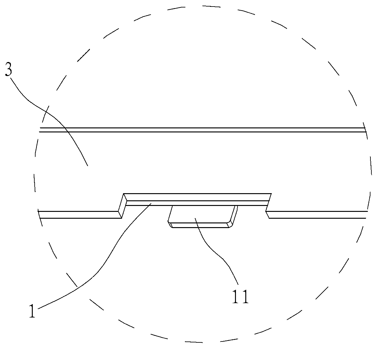
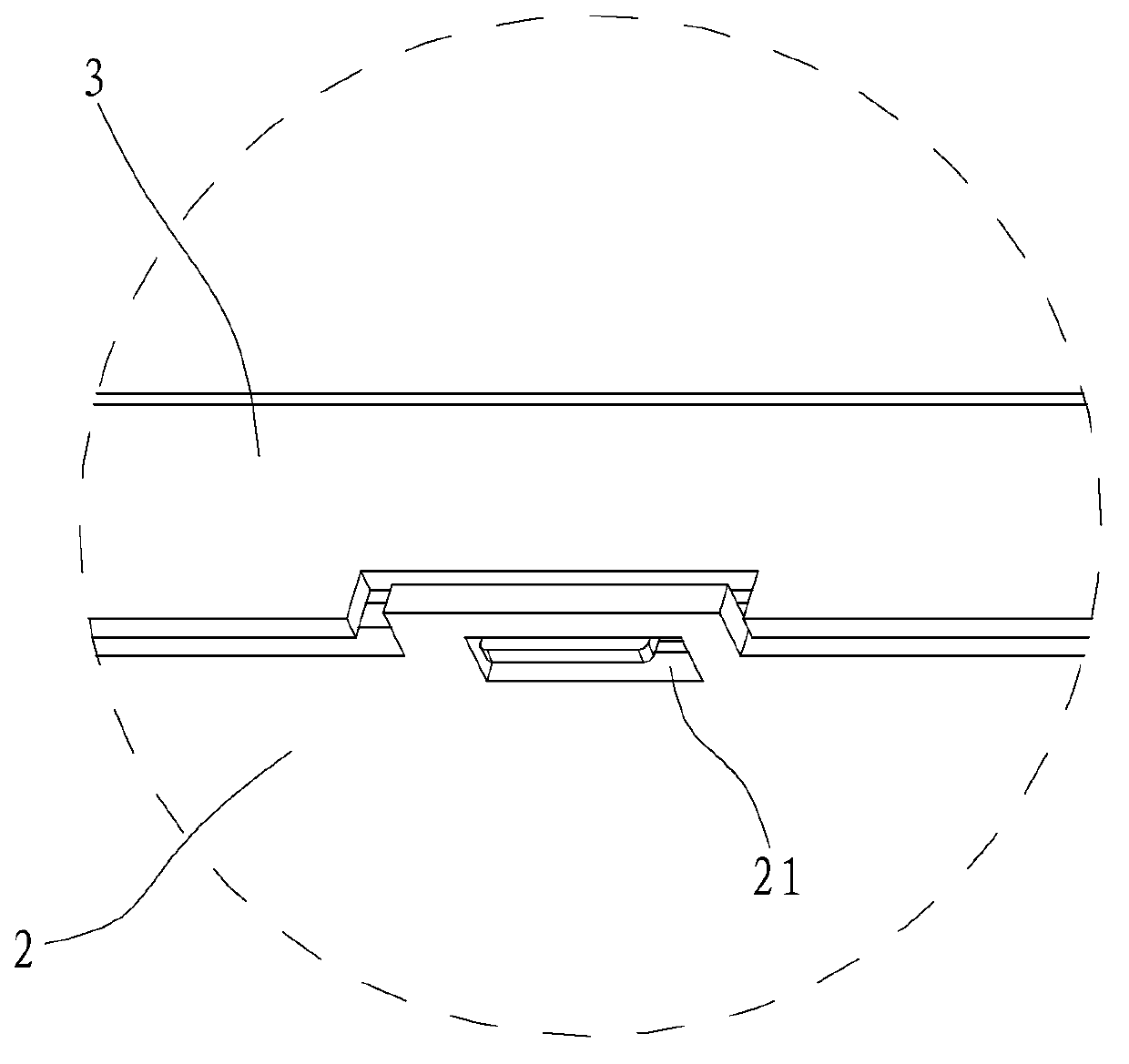
[0044] combine figure 1 and figure 2 , a diaphragm positioning structure, including a back plate, a positioning member 1, and a diaphragm 2, the positioning member 1 is attached to the inner end surface of the vertical edge 3 of the back plate, the positioning member 1 has a raised portion 11, and the membrane The sheet 2 has a positioning hole 21 adapted to the raised portion 11 , and the diaphragm 2 is positioned through the positioning hole 21 in cooperation with the raised portion 11 .

Embodiment 2

[0046] combine Figure 3 to Figure 5 , a diaphragm positioning structure, including a back plate, a positioning member 1, and a diaphragm 2, the positioning member 1 is attached to the inner end surface of the vertical edge 3 of the back plate, the positioning member 1 has a raised portion 11, and the membrane The sheet 2 has a positioning hole 21 adapted to the raised portion 11 , and the diaphragm 2 is positioned through the positioning hole 21 in cooperation with the raised portion 11 .

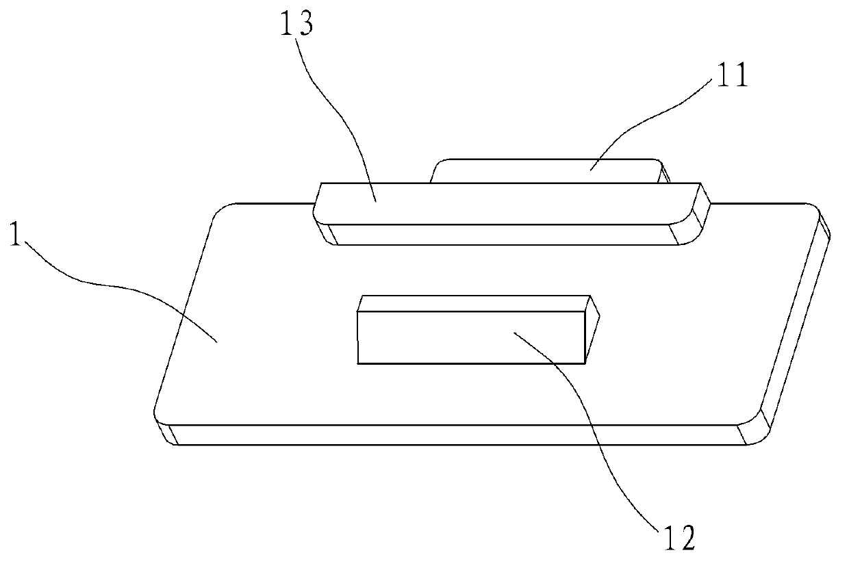
[0047] The positioning member 1 is provided with a buckle 12, and the vertical edge 3 of the backboard is provided with a slot 32 that is compatible with the buckle 12; the positioning member 1 is provided with a positioning rib 13, and the edge of the backboard The vertical edge 3 is provided with a positioning groove 33 adapted to the positioning rib 13 .

[0048] Or, according to the needs of actual assembly, a card slot can also be provided on the positioning member 1, and a buckle ma...

Embodiment 3

[0050] combine Figure 6 to Figure 9 , a diaphragm positioning structure, including a back plate, a positioning member 1, and a diaphragm 2, the positioning member 1 is attached to the inner end surface of the vertical edge 3 of the back plate, the positioning member 1 has a raised portion 11, and the membrane The sheet 2 has a positioning hole 21 adapted to the raised portion 11 , and the diaphragm 2 is positioned through the positioning hole 21 in cooperation with the raised portion 11 .

[0051]The positioning member 1 is provided with a buckle 12, and the vertical edge 3 of the backboard is provided with a slot 32 that is compatible with the buckle 12; the positioning member 1 is provided with a positioning rib 13, and the edge of the backboard The vertical edge 3 is provided with a positioning groove 33 adapted to the positioning rib 13 .

[0052] The positioning part 1 is also equipped with a bracket 4, and a positioning part is formed between the vertical edge 3 of the...


PUM


Abstract

The invention discloses a membrane positioning structure, a backlight module with the membrane positioning structure and a display device. The membrane positioning structure comprises a back plate, a positioning part and a membrane. The positioning part is attached to the inner end face of the vertical edge of the back plate and is provided with a protrusion, the membrane is provided with a positioning hole fitted with the protrusion, and the positioning hole matches with the protrusion to position the membrane. The positioning part of the membrane positioning structure is attached to the inner end face of the vertical edge of the back plate, the protrusion on the positioning part matches with the positioning hole to position the membrane, the positioning structure is completed at the edge of the back plate, occupied space is small, shape of light guide plate is not influenced, and a notch need not be arranged on the light guide plate for avoiding. The vertical edge of the back plate is purely erected without any deformation, thickness of a space occupied by the vertical edge of the back plate is reduced to smallest, namely size of thickness of the vertical edge only, and narrow-edged development of a liquid crystal display television is facilitated.

Description

technical field [0001] The invention relates to a diaphragm positioning structure of a backlight module, and a backlight module and a display device having the diaphragm positioning structure. Background technique [0002] The backlight module is mainly composed of light source, reflector, optical film, light guide plate, back plate and other related components. The main function of the optical film with prism structure is to condense light. Some types of optical brightening film and polarizer can reflect, recycle and reuse the polarized light that cannot pass through the polarizer to improve the effective utilization of light. This requires that the positioning and installation of the optical diaphragm be accurate, and the installation accuracy is high. [0003] At present, during the assembly process of the backlight module, the positioning of the optical film is done by the rivet posts on the back plate. The method of positioning the diaphragm by the rivet column takes ...

Claims


Application Information

Patent Timeline
Patent Type & Authority Applications(China)
IPC IPC(8): F21V17/10F21S8/00G02F1/13357H04N5/64
Inventor 唐志强陆宾林
Owner HISENSE VISUAL TECH CO LTD
Why Eureka
Try Eureka