

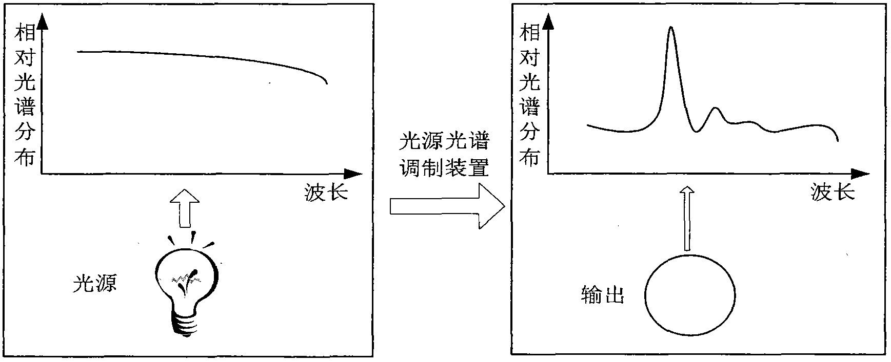
Light source spectrum modulating device
A spectrum modulation and light source technology, applied in the field of optical testing, can solve problems such as lack of means, inability to fully control the output spectrum intensity, and large differences in spectral distribution
- Summary
- Abstract
- Description
- Claims
- Application Information
AI Technical Summary
Benefits of technology
Problems solved by technology
Method used
Image


Examples
Embodiment Construction
[0022] Specific embodiments of the present invention will be described in detail below in conjunction with the accompanying drawings. In the following description, for purposes of explanation and not limitation, specific details are set forth in order to provide a thorough understanding of the invention. It will be apparent, however, to one skilled in the art that the present invention may be practiced in other embodiments that depart from these specific details.
[0023] It should be noted here that, in order to avoid obscuring the present invention due to unnecessary details, only the device structure and / or processing steps closely related to the solution according to the present invention are shown in the drawings, and the steps related to the present invention are omitted. Invent other details that don't really matter.
[0024] Embodiments of the present invention will be described below with reference to the drawings.
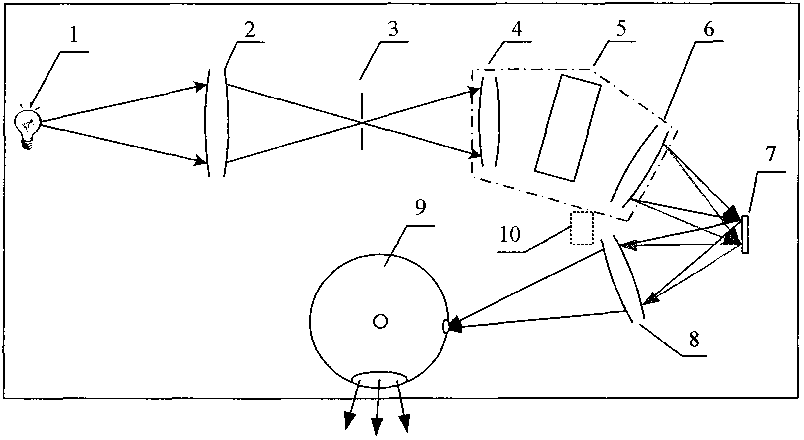
[0025] like figure 1 Shown is a schematic struct...
PUM
 Abstract
Description
Claims
Application Information